•
Always use an ESD grounding strap when you are handling components that are subject
to ESD damage, and make sure that it is in direct contact with your skin.
If a grounding strap is not available, hold the component in its antistatic bag (see Figure
76 on page 237) in one hand and touch the exposed, bare metal of the switch with the
other hand immediately before inserting the component into the switch.
WARNING: For safety, periodically check the resistance value of the ESD strap. The
measurement must be in the range of 1 through 10 Mohms.
•
When handling any component that is subject to ESD damage and that is removed
from the chassis, make sure the equipment end of your ESD strap is attached to the
ESD point on the chassis.
If no grounding strap is available,touchthe exposed, bare metal of the switch to ground
yourself before handling the component.
•
Avoid contactbetween the component that is subject to ESD damage and your clothing.
ESD voltages emitted from clothing can damage components.
•
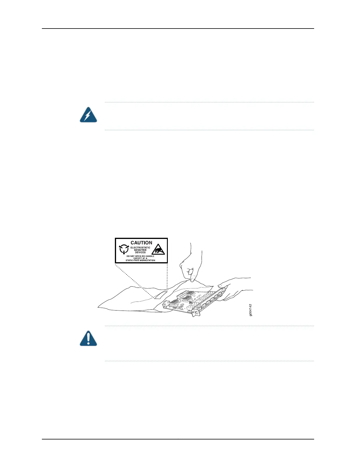
When removing or installing a component that is subject to ESD damage, always place
it component-side up on an antistatic surface, in an antistatic card rack, or in an
antistatic bag (see Figure 76 on page 237). If you are returning a component, place it in
an antistatic bag before packing it.
Figure 76: Place a Component into an Antistatic Bag
CAUTION: ANSI/TIA/EIA-568 cables such as category 5e and category 6 can get
electrostatically charged. In order to dissipate this charge, always ground the cables
to a suitable and safe earth ground before connecting them to the system.
Related Topics General Safety Guidelines and Warnings for EX Series Switches on page 207•
• See Rear Panel of an EX2200 Switch for the ESD point location.
• See Rear Panel of an EX3200 Switch on page 8 for the ESD point location.
• See Rear Panel of an EX4200 Switch on page 11 for the ESD point location.
• See Front Panel of an EX4500 Switch for the ESD point location.
237Copyright © 2010, Juniper Networks, Inc.
Chapter 20: Power and Electrical Safety Information