•
The equipment is suitable for installation as part of the Common Bonding Network
(CBN).
•
The equipment is suitable for installation in locations where the National Electrical
Code (NEC) applies.
•
The battery return connection is to be treated as an Isolated DC return (DC-I), as
defined in GR-1089-CORE.
Related
Documentation
Agency Approvals for EX Series Switches•
• Compliance Statements for Acoustic Noise for EX Series Switches
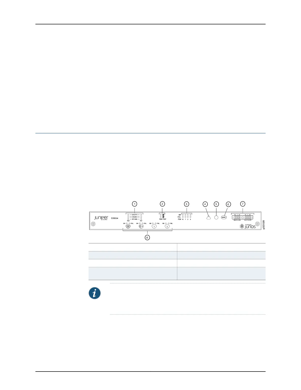
Craft Interface in an EX9200 Switch
The craft interface enables you to view status and troubleshooting information at a
glance and to perform many system control functions. The craft interface is located on
the front panel of the switch. It contains LEDs and on and off buttons for switch
components, the alarm relay contacts, and an alarm cutoff button.
Figure 11 on page 20 shows the craft interface in an EX9204 switch. Figure 12 on page 21
shows the craft interface in an EX9208 switch.Figure 13 on page 21 shows the craft
interface in an EX9214 switch.
Figure 11: Craft Interface in an EX9204 Switch
5—1— Major alarm LEDHost subsystem LEDs
6—2— Alarm cutoff/lamp test buttonFan LEDs
7—3— Alarm relay contactsPower supply LEDs
8—4— LEDs and control buttons for Switch Fabric
and Line cards
Minor alarm LED
NOTE: You can install a line card or an SF module in the multifunctional slot
labeled 1|0 in EX9204 switches. The corresponding LED displays information
depending on the hardware installed in that slot.
Copyright © 2016, Juniper Networks, Inc.20
Hardware Topics for Aloha Line Card