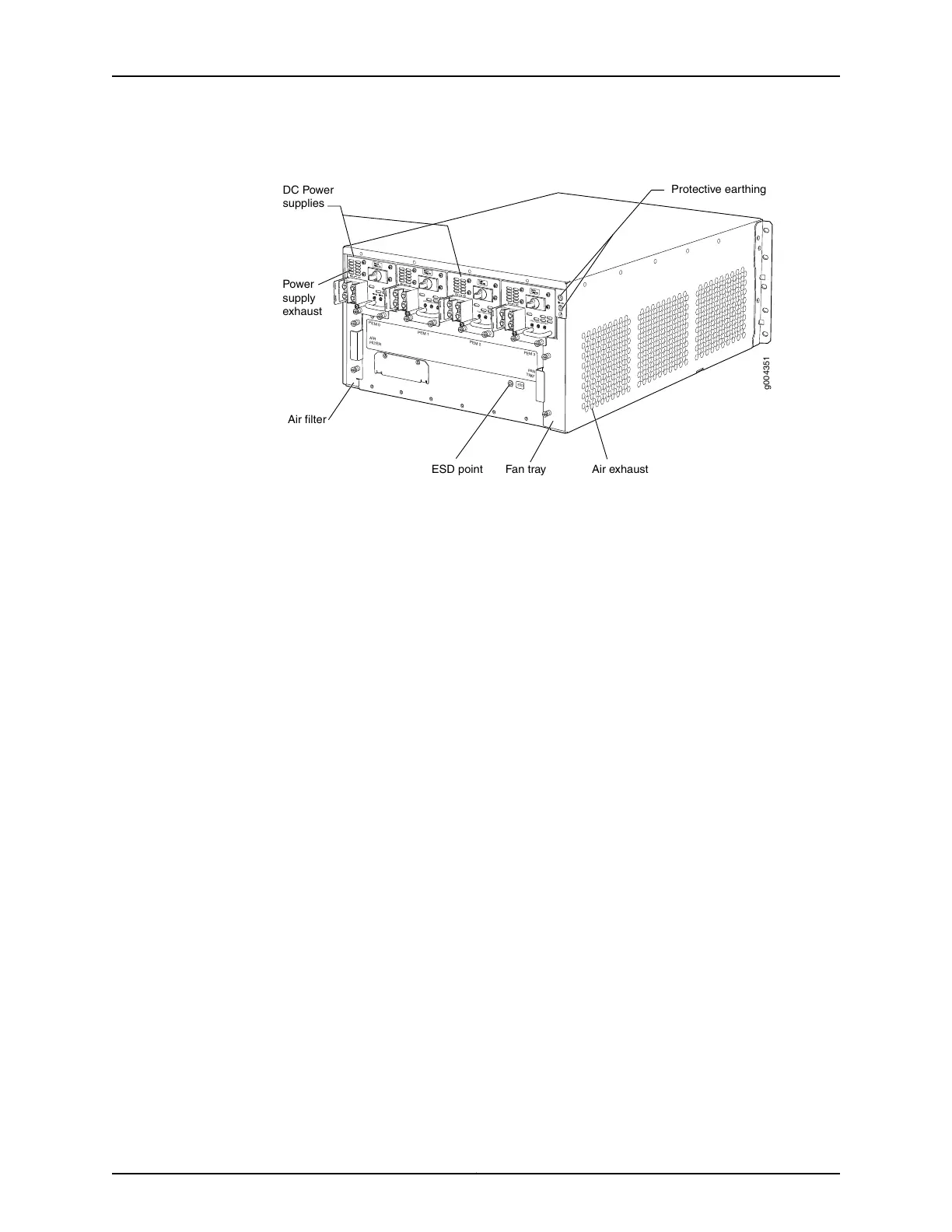
Figure 25: Rear View of a DC-Powered EX9204 Switch
PEM 3
PEM 2
PEM 1
PEM 0
AIR
FI
L
TER
FAN
TRAY
g004351
DC Power
supplies
Fan tray
Air filter
Power
supply
exhaust
Protective earthing
Air exhaustESD point
ESD
INPUTOK
PWR OK
BKR ON
INPUTOK
PWR OK
BKR ON
INPUTOK
PWR OK
BKR ON
INPUTOK
Host Subsystem
Switching and routing functionality, system management, and system control functions
of an EX9204 switch are performed by the host subsystem. The host subsystem consists
of a Routing Engine functioning together with a Switch Fabric.
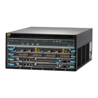
An EX9204 is a 4-slot chassis that provides two dedicated slots—labeled 1 and 2—for
line cards, one dedicated slot—labeled 0—for a host subsystem, and one multifunction
slot—labeled 1|0—for either a line card or a host subsystem.
You can install either one or two host subsystems in an EX9204 switch. A
base-configuration EX9204 switch has one host subsystem. A redundant-configuration
EX9204 switch has a second host subsystem. For more information, see EX9204 Switch
Configurations.
Line Cards
Line cards are field-replaceable units (FRUs) that you can install in the line card slots
and in the multifunctional slot on the front of the switch chassis. All line cards are
hot-removable and hot-insertable.
You can install up to three line cards in an EX9204 switch. Each EX9204 switch has two
dedicated line card slots—labeled 1 and 2—and a multifunction slot—labeled 1|0—that
you can use for either a line card or a host subsystem.
The line cards in EX9204 switches combine a Packet Forwarding Engine and Ethernet
interfaces in a single assembly. Table 29 on page 72 lists the line cards available for
EX9204 switches.
71Copyright © 2016, Juniper Networks, Inc.
Chapter 3: Updated EX9204 Topics