Related
Documentation
Rack Requirements for an EX9200 Switch•
• Cabinet Requirements for an EX9200 Switch
• Mounting an EX9200 Switch on a Rack or Cabinet Using a Mechanical Lift
• Installing and Removing EX9214 Switch Hardware Components
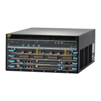
EX9214 Switch Hardware and CLI Terminology Mapping
This topic describes the hardware terms used in EX9214 switch documentation and the
corresponding terms used in the Junos OS CLI. See Table 40 on page 100.
Table 40: CLI Equivalents of Terms Used in Documentation for EX9214 Switches
Additional Information
Item in
DocumentationValue (CLI)Description (CLI)
Hardware
Item (CLI)
“Chassis Physical
Specifications of an
EX9214 Switch” on
page 96
Switch chassis–EX9214Chassis
Midplane in an EX9200
Switch
Switch midplane–EX9214-BPMidplane
“Craft Interface in an
EX9200 Switch” on
page 20
Craft interface–Front Panel DisplayFPM Board
•
AC Power Supply in an
EX9214 Switch
•
DC Power Supply in an
EX9214 Switch
AC or DC power supplyn is a value in the range of
0–3. The value corresponds
to the power supply slot
number.
One of the following:
•
PS 4.1 kW;
200-240 V AC in
•
DC 2.4 kW Power
Entry Module
PEM(n)
Routing Engine Module in
an EX9200 Switch
RE modulen is a value in the range 0–1.
In base configuration, only
one entry appears.
In a redundant configuration,
two entries appear; one for
each Routing Engine module
(RE module) installed in the
chassis.
RE-S-EX9200-1800X4Routing
Engine (n)
Copyright © 2016, Juniper Networks, Inc.100
Hardware Topics for Aloha Line Card