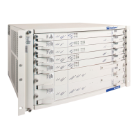
Alarm Relay Contacts
The craft interface has two alarm relay contacts for connecting the switch to external
alarm devices. Whenever a system condition triggers either the critical (major alarm) or
warning (minor alarm) alarm on the craft interface, the alarm relay contacts are also
activated. The alarm relay contacts are located on the upper right of the craft interface.
Figure 14 on page 25 shows the alarm relay contacts in EX9200 switches.
Figure 14: Alarm Relay Contacts in EX9200 Switches
g022029
Craft Interface panel
Alarm
relay
contacts
Related
Documentation
EX9204 Switch Hardware Overview on page 69•
• EX9208 Switch Hardware Overview on page 81
• EX9214 Switch Hardware Overview on page 91
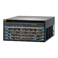
EX9200-2C-8XS Line Card
The line cards in EX9200 switches combine a Packet Forwarding Engine and Ethernet
interfaces in a single assembly. Line cards are field-replaceable units (FRUs) that you
can install in the line card slots on the front of the switch chassis. Line cards are
hot-insertable and hot-removable: You can remove and replace them without powering
off the switch or disrupting switch functions.
This topic describes:
•
Line Card Models on page 25
•
Line Card Components on page 26
Line Card Models
Table 13 on page 26 shows the model number, description of the line card model, and
the Junos OS release in which the line card was first supported.
25Copyright © 2016, Juniper Networks, Inc.
Chapter 2: Updated Common EX9200 Topics