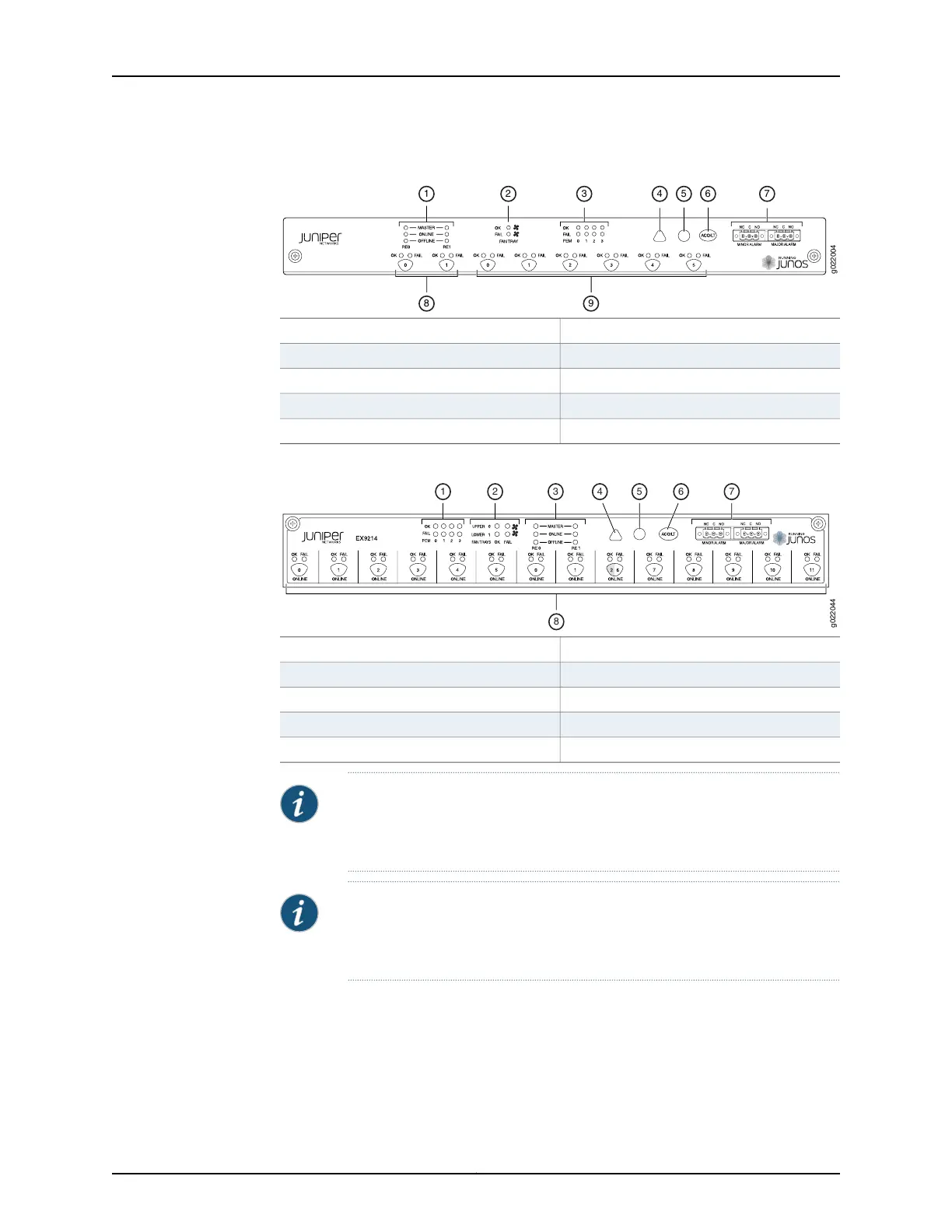
Figure 12: Craft Interface in an EX9208 Switch
6—1— Alarm cutoff/lamp test buttonHost subsystem LEDs
7—2— Alarm relay contactsFan LEDs
8—3— Switch Fabric LEDs and control buttonsPower supply LEDs
9—4— Line card LEDs and control buttonsMinor alarm LED
5—Major alarm LED
Figure 13: Craft Interface in an EX9214 Switch
6—1— Alarm cutoff/lamp test buttonPower supply LEDs
7—2— Alarm relay contactsFan LEDs
8—3— Switch Fabric LEDs and control buttonsHost subsystem LEDs
9—4— Line card LEDs and control buttonsMinor alarm LED
5—Major alarm LED
NOTE: You can install a line card or a Switch Fabric module (SF module) in
slot nine—labeled 2 | 6. The corresponding LED displays information
depending on the hardware installed in that slot.
NOTE: At least one Switch Fabric module (SF module) with a Routing Engine
module (RE module) must be installed in the switch for the craft interface
to obtain power.
The craft interface has the following components:
•
Host Subsystem LEDs on page 22
•
Fan LEDs on page 22
•
Power Supply (PEM) LEDs on page 23
21Copyright © 2016, Juniper Networks, Inc.
Chapter 2: Updated Common EX9200 Topics