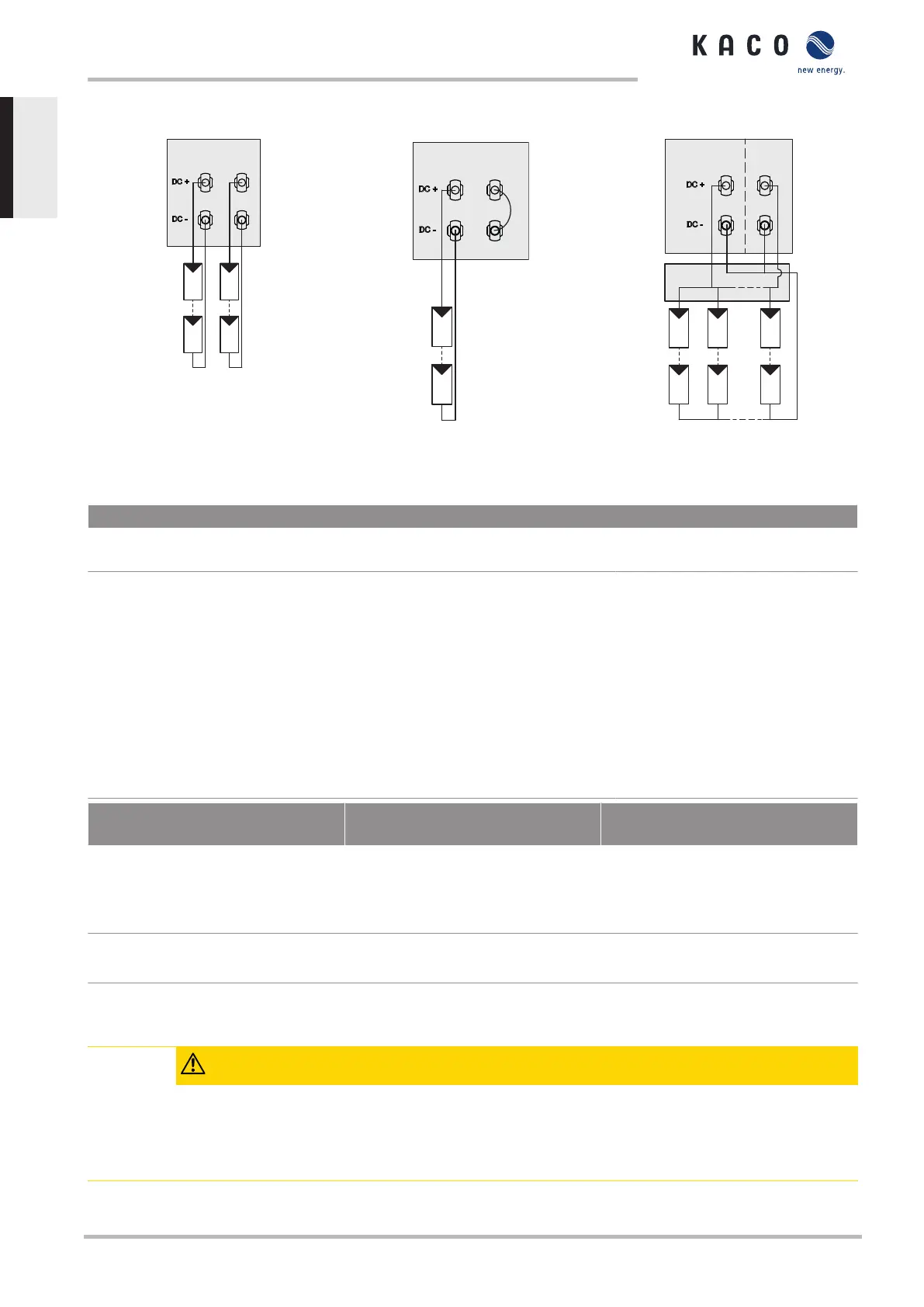
7.5.3 Recommended standard connection
Fig.21: Recommended standard con-
nection
Fig.22: Parallel input with Y-adapter,
short-circuits the unused MPP Tracker
B
Fig.23: One generator parallel on both
MPP trackers
Possible wiring variants
2 PV generators for each MPP
tracker
1 PV generator for one tracker. The second
tracker is deactivated
1 PV generator parallel on both MPP
trackers
The MPP voltages of the two DC
strings can be different. They are
supplied by separate, independ-
ently operating MPP trackers
(MPP trackers A and B).
If one of the MPP trackers (A or B) is not used,
then it must be short-circuited, otherwise faults
can occur during the self-test of the unit and the
feed-in operation is not guaranteed. The short-
circuiting of an MPP tracker does not result in
the device being damaged.
The DC inputs can also be connected
in parallel. In this case, only lines with
the same MPP voltage may be con-
nected in parallel. (U
n1
=U
n2
=U
nm
).
The maximum permissible rated cur-
rent (DC) doubles with parallel con-
nection of both MPP trackers.
In case of a parallel input connection,
MPP trackers A and B must be
bridged. Parallel operation is auto-
matically recognised by the inverter
Number of modules per string: n
1
=n
2
Number of modules per string: n
1
=n
m
Number of modules per string:
n
1
=n
2
=n
m
P
max :
per string < 0.5 * max. recommen-
ded PV generator power
MPP tracker A+B together < max. re-
commended PV generator power
P
max:
Per string < 0.5*max. recommen-
ded PV generator power P
max
on the
MPP tracker used < max. power per
MPP tracker
P
max :
max. recommended PV generator
power
MPP tracker A+B together < max. re-
commended PV generator power
I
max:
Depending on PV generator
The input current per MPP tracker must not be exceed 11 A.
I
max:
≤ 2 * max. rated current (DC)
Tab.3: Electrical data of the connection
7.5.4 Designing the PV generator
CAUTION
Damage to components due to faulty configuration
In the expected temperature range of the PV generator, the values for the no-load-voltage and the short
circuit current must never exceed the values for U
dcmax
and I
scmax
in accordance with the technical data.
› Observe limit values in accordance with the technical data.
KACO blueplanet 3.0 TL3 KACO blueplanet 4.0 TL3 KACO blueplanet 5.0 TL3 KACO blueplanet 6.5 TL3 KACO
blueplanet 7.5 TL3 KACO blueplanet 8.6 TL3 KACO blueplanet 9.0 TL3 KACO blueplanet 10.0 TL3
Page 22
EN

 Loading...


