NOTE
Type and configuration of the PV modules.
Connected PV modules must be dimensioned for the DC system voltage in accordance with IEC 61730 Class
A, but at least for the value of the AC grid voltage
NOTE
Sizing of the PV generator
The device is designed with a reserve of DC short-circuit current withstand capability. This allows oversizing
of the connected PV generator. The absolute limit for the PV generator is the value of the maximum short
circuit current (lsc max) and maximum open circuit voltage (Uoc max).
7.5.5 Connecting the PV generator
DANGER
Risk of fatal injury due to electric shock!
Severe injury or death will result if the live connections are touched. When there is sunlight present on the
PV generator, there is DC voltage on the open ends of the DC cables.
› Only touch the PV generator cables on the insulation. Do not touch the exposed ends of the cables.
› Avoid short circuits.
› Do not connect any strings with a ground fault to the device.
CAUTION
Damage to the PV generator in case of faulty configuration of the DC connector.
A faulty configuration of the DC connector (polarity +/-) causes equipment damage in the DC connection if
it is connected permanently.
› Please check polarity (+/-) of the DC connector before connecting the DC generator.
› Before using the solar modules, check the vendor’s calculated voltage values against those actually
measured. The DC voltage of the PV system must not exceed the maximum no-load voltage at any
time.
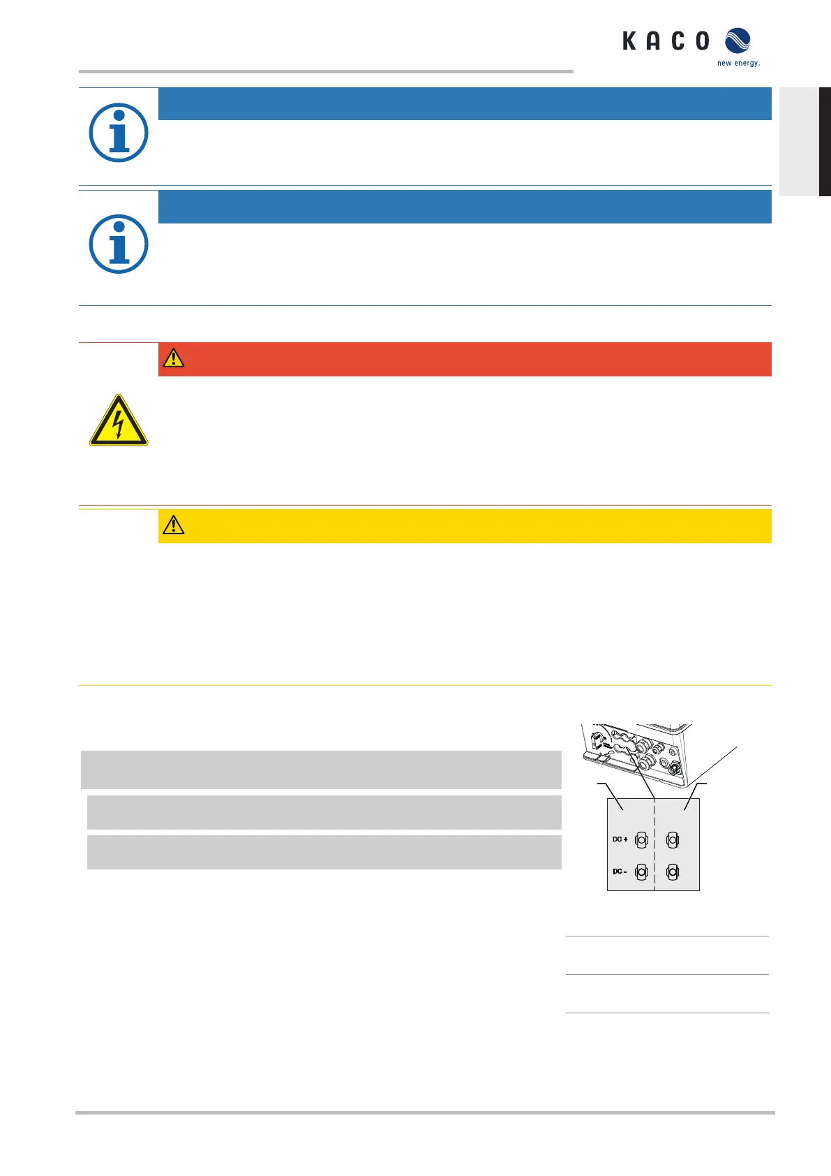
Connecting the PV generator
↻ DC plug connector configured and PV generator checked to ensure there is no
ground fault.
1 Remove protective caps from the required DC connection plugs on the under-
side of the device.
2 Connect the the DC plug connectors to the DC positive and DC negative connect-
ors in pairs.
» The device is connected to the PV generator.
Fig.24: Connection for DC positive
and DC negative
1 DC-connection to MPP
tracker A
2 DC-connection to MPP
tracker B
KACO blueplanet 3.0 TL3 KACO blueplanet 4.0 TL3 KACO blueplanet 5.0 TL3 KACO blueplanet 6.5 TL3 KACO
blueplanet 7.5 TL3 KACO blueplanet 8.6 TL3 KACO blueplanet 9.0 TL3 KACO blueplanet 10.0 TL3
Page 23
EN
 Loading...


