Triggering 9-13
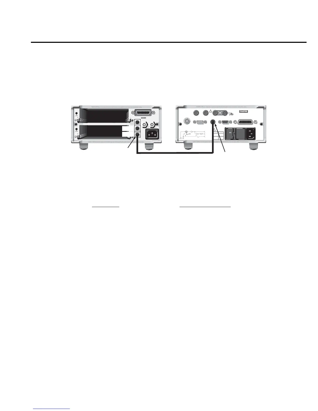
The trigger link connections for this test system are shown in Figure 9-8. The trigger link of
Model 6514 is connected to the trigger link (IN or OUT) of the switching mainframe. Note that
with the default trigger settings of the switching mainframe, line #1 is an input and line #2 is an
output.
For this example, Model 6514 and switching mainframe are configured as follows:
To store readings in Model 6514 buffer, press STORE and set the buffer size to 10. When
ENTER is pressed, the asterisk (*) annunciator turns on to indicate the buffer is enabled (see
Section 8 for details on buffer operation).
To start the test, press STEP on the switching mainframe to take it out of idle and start the
scan. The switching mainframes output pulse triggers Model 6514 to take a reading and store it.
Model 6514 then sends an output trigger pulse to the switching mainframe to close the next
channel. This process continues until all 10 channels are scanned, measured and stored.
Details of this testing process are explained in the following paragraphs and are referenced to
the operation model shown in Figure 9-9.
Model 6514 Switching Mainframe
Factory Defaults Restored Factory Defaults Restored
Trig-In Event = TLink Scan List = 1!1-1!10
Trigger Input Line = #2 Number of Scans 1
Trigger Output Line = #1 Channel Spacing = TrigLink
Trigger Output Event = ON
Trigger Count = 10
Trigger Delay = Auto
RS232DIGITAL I/O
PREAMP
250V PK
2V
OUTPUT
COMMON CHASSIS
120
FUSE LINE
630mA
LINE RATING
50, 60Hz
60 VA MAX
T
(SB)
100 VAC
120 VAC
315mAT
(SB)
220 VAC
240 VAC
INPUT 250V PK
IEEE-488
(CHANGE IEEE
WITH FRONT PANEL MENU)
TRIGGER LINK
!
!
MADE IN
U.S.A.
V, GUARD
(PROGRAMMABLE)
OFF
ON
GUARD
(FOLLOWS
INPUT)
(INTERNAL)
INPUT PREAMP
10K
PREAMP
OUT
2V
OUTPUT
COM
MADE IN USA
7001 or 7002 Switch System
Model 6514 Electrometer
OUT
IN
Trigger
Link
Trigger
Link
Trigger
Link Cable
(8501)
Figure 9-8
Trigger
link con-
nections