Measurement Concepts 2-11
Input protection
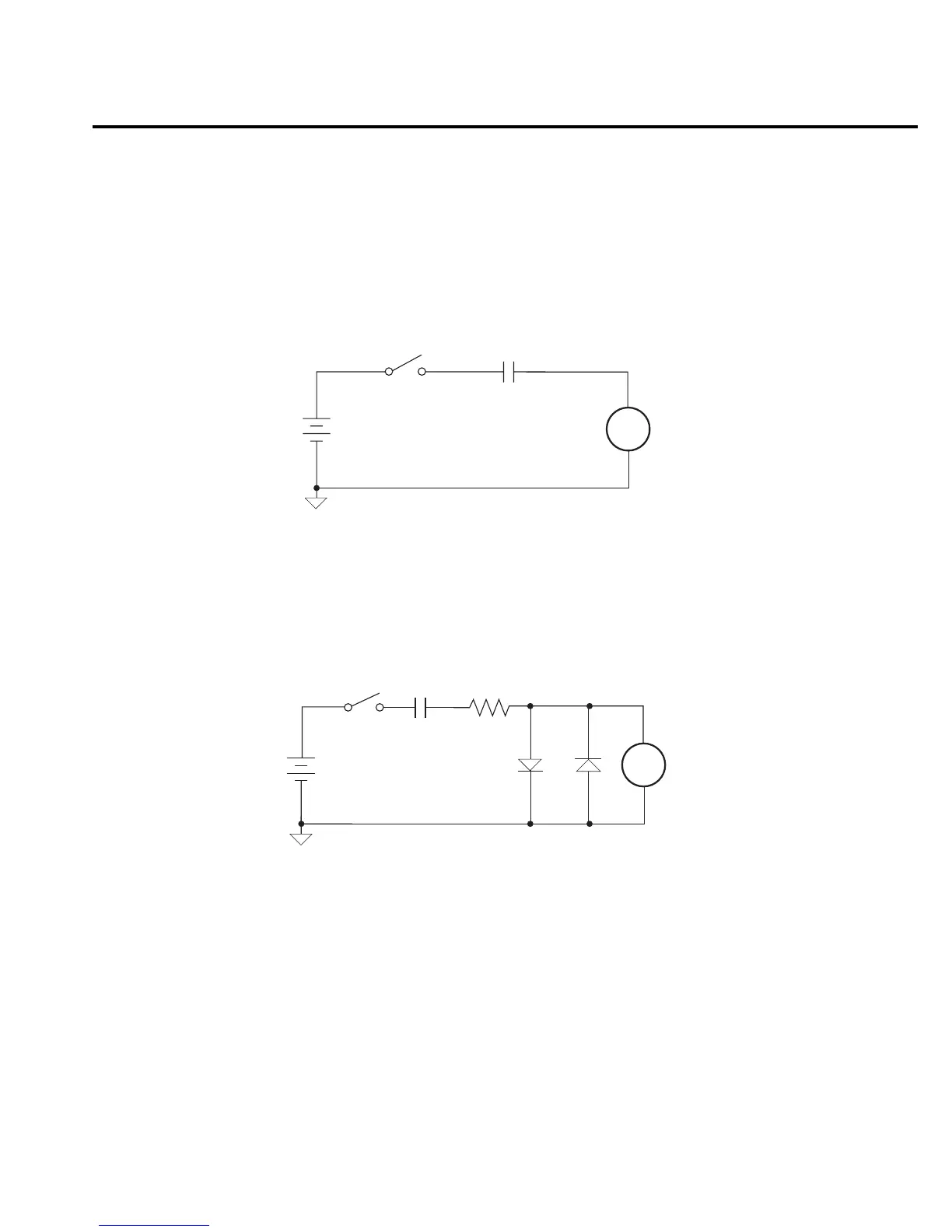
Model 6514 incorporates protection circuitry against nominal overload conditions. However,
a high voltage (>250V) and resultant current surge could damage the input circuitry. A typical
test circuit to measure the leakage current of a capacitor is shown in Figure 2-7. When Switch S
is closed, an initial charging current will flow and the high voltage will be seen across the input
of Model 6514.
Adding a resistor and two diodes (1N3595) as shown in Figure 2-8 will provide considerable
extra protection. The resistor must be large enough to limit the current through the diodes to
10mA or less, and be large enough to withstand the supply voltage. The protection circuit should
be enclosed in a light-tight conductive shield.
Floating measurements
With the ground link between the COMMON and CHASSIS banana jack terminals removed,
Model 6514 can perform floating measurements up to 500V above chassis ground. These mea-
surements can result in safety concerns.
Capacitor
Under Test
S
V
6514
Ammeter
A
Figure 2-7
Capacitor test circuit
without protection
Protection Circuit
HI
6514
Ammeter
LO
Capacitor
Under Test
S
V
D1 D2
A
R
Figure 2-8
Capacitor test
circuit with
protection