11-10 Digital I/O, Analog Outputs, and External Feedback
Since the preamp output signal is not corrected during calibration, gain error of up to 15%
may appear at this output, depending on function and range selection. For all volts ranges,
preamp output accuracy is typically 10ppm.
WARNING High voltage may be present between the preamp output and common ter-
minals depending on the input signal (see Table 11-3).
CAUTION Connecting preamp output, common, or 2V analog output to earth while
floating the input may damage the instrument.
Note that the preamp out output resistance is 1Ω. The output resistance appears between input
low and analog output low to keep the resistor out of the loop when using external feedback ele-
ments. To keep loading errors under 0.1%, the device connected to the preamp output should
have a minimum input impedance of 100k.
CAUTION To prevent damage to Model 6514, do not connect a device to preamp out
that will draw more than ±100µA. For example, at 200V, the impedance
connected to preamp out must be at least 2MΩ (200V/100µA = 2MΩ).
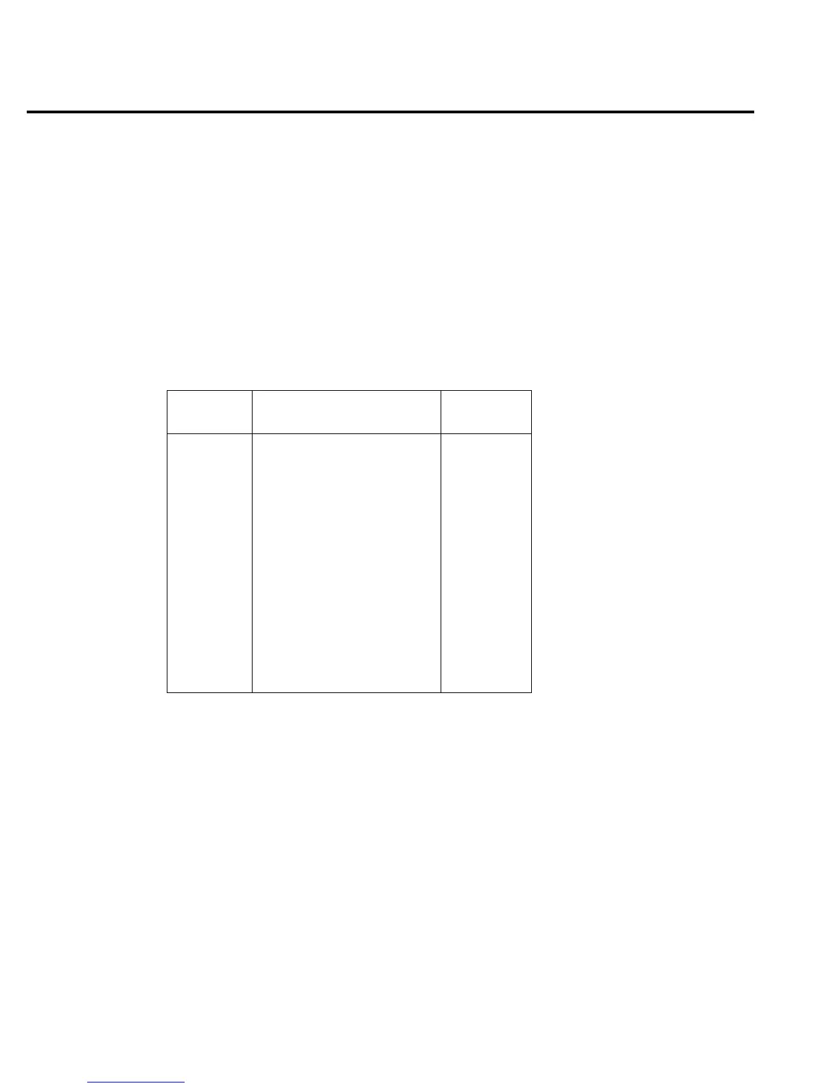
Table 11-3
Full-range preamp out values
Function Range
Full-range
value
Volts 2V 2V
20V 20V
200V 200V
Amps 2nA, 2µA, 2mA 2V
20pA, 20nA, 20µA, 20mA 20V
200pA, 200nA, 200µA 200V
Ohms 2kΩ, 2MΩ, 2GΩ 2V
20kΩ, 20MΩ, 20GΩ 20V
200kΩ, 200MΩ, 200GΩ 200V
Coulombs 20nC, 2µC 20V
200nC, 20µC 200V