9-12 Triggering
Output trigger specifications
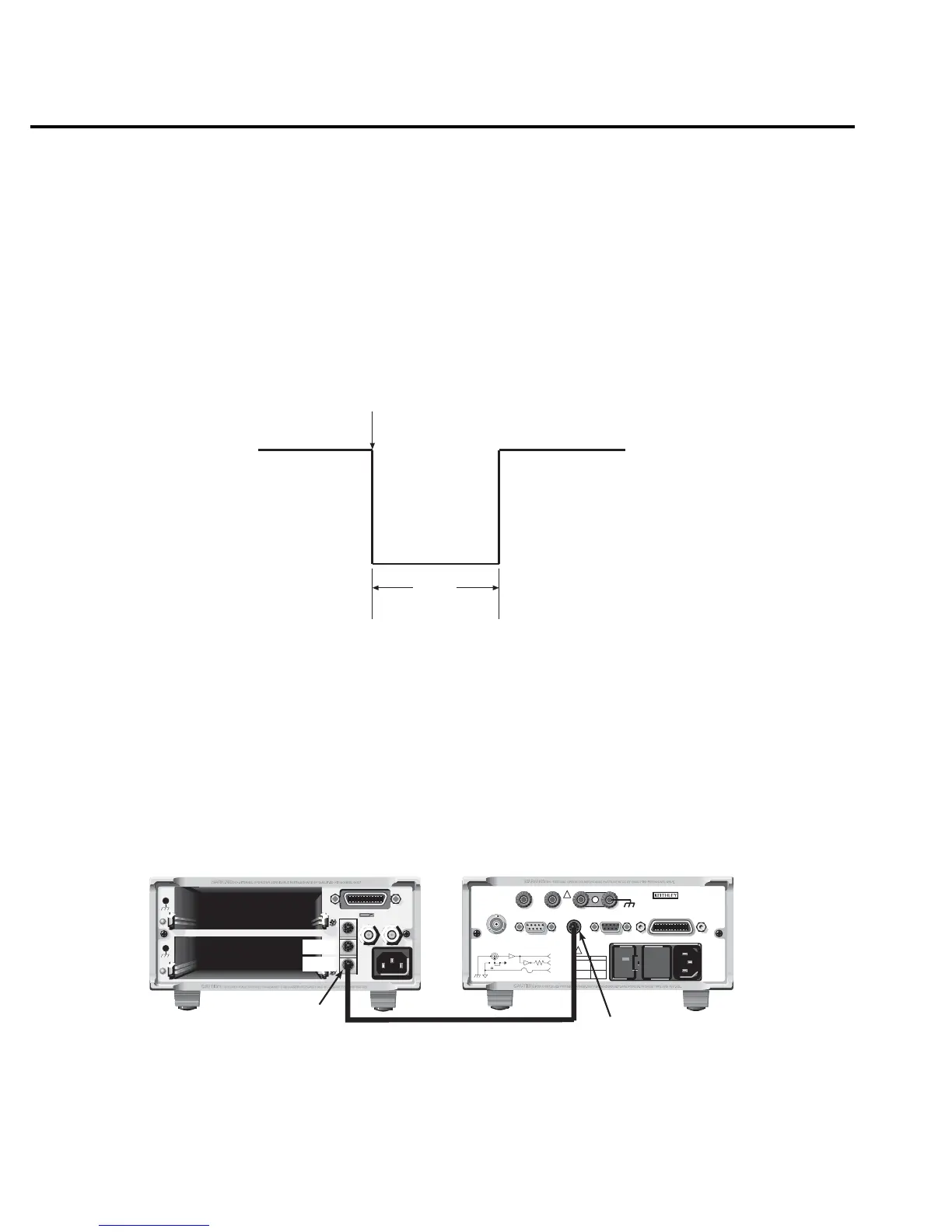
Model 6514 can be programmed to output a trigger immediately after a measurement and/or
when operation leaves the trigger layer of the trigger model. The output trigger provides a
TTL-compatible output pulse that can be used to trigger other instruments. The specifications
for this trigger pulse are shown in Figure 9-6. A trigger link line can source 1mA and sink up to
50mA.
External trigger example
In a simple test system, you may want to close a switching channel and measure the resistance
of a DUT connected to that channel. Such a test system is shown in Figure 9-7, which uses a
Model 6514 to measure 10 DUTs switched by a Model 7011 multiplexer card in a Model 7001
or 7002 switch system.
Meter
Complete
TTL High
(3.4V Typical)
TTL Low
(0.25V Typical)
10µs
Minimum
Figure 9-6
Trigger link output
pulse specifications
RS232DIGITAL I/O
PREAMP
250V PK
2V
OUTPUT
COMMON CHASSIS
120
FUSE LINE
630mA
LINE RATING
50, 60Hz
60 VA MAX
T
(SB)
100 VAC
120 VAC
315mAT
(SB)
220 VAC
240 VAC
INPUT 250V PK
IEEE-488
(CHANGE IEEE
WITH FRONT PANEL MENU)
TRIGGER LINK
!
!
MADE IN
U.S.A.
V, GUARD
(PROGRAMMABLE)
OFF
ON
GUARD
(FOLLOWS
INPUT)
(INTERNAL)
INPUT PREAMP
10K
PREAMP
OUT
2V
OUTPUT
COM
MADE IN USA
7001 or 7002 Switch System
Model 6514 Electrometer
OUT
IN
Trigger
Link
Trigger
Link
Trigger
Link Cable
(8501)
Figure 9-7
DUT test
system