Volts and Ohms Measurements 3-9
Volts and ohms measurement considerations
NOTE Since Model 6514 uses the source I measure V (calculate R) technique to measure
resistance, measurement considerations that apply to the volts function also apply to
the ohms function.
Some considerations for making accurate volts and ohms measurements are summarized as
follows. Additional measurement considerations are covered in Appendix C. For comprehensive
information on precision measurements, refer to the Low Level Measurements handbook, which
is available from Keithley Instruments.
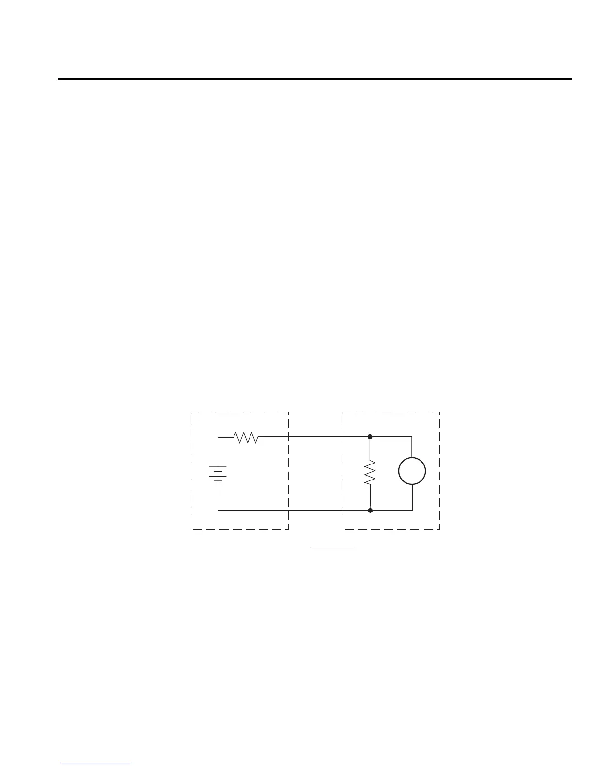
Loading effects
Circuit loading can be detrimental to high-impedance voltage measurements. To see how
meter loading can affect accuracy, refer to Figure 3-4. R
S
represents the resistance component
of the source, while R
IN
represents the input resistance of the meter. The percent error due to
loading can be calculated using the formula in the illustration. To keep the error under 0.1%, the
input resistance (R
IN
) must be about 1000 times the value of the source resistance (R
S
). The input
resistance of Model 6514 is >200TΩ. Therefore, to keep the error under 0.1%, the source resis-
tance of the measured voltage must be <200GΩ.
Cable leakage resistance
In an unguarded voltage measurement, leakage current occurs in the input triax cable between
the center conductor (HI) and the inner shield (LO). This leakage resistance shunts the voltage
source to be measured. If the resistance of the source is not significantly less than the leakage
resistance of the cable, measurement errors will occur.
The effects of leakage resistance can be eliminated by using guard to make high impedance
voltage measurements. See “Guarding Input Cable” for more information. In general, guarding
should be used when DUT resistance is 10
9
Ω or greater.
Source
R
s
V
E
s
R
IN
Meter
% Error =
100R
S
R
S
+ R
IN
Figure 3-4
Meter loading