Measurement Concepts 2-9
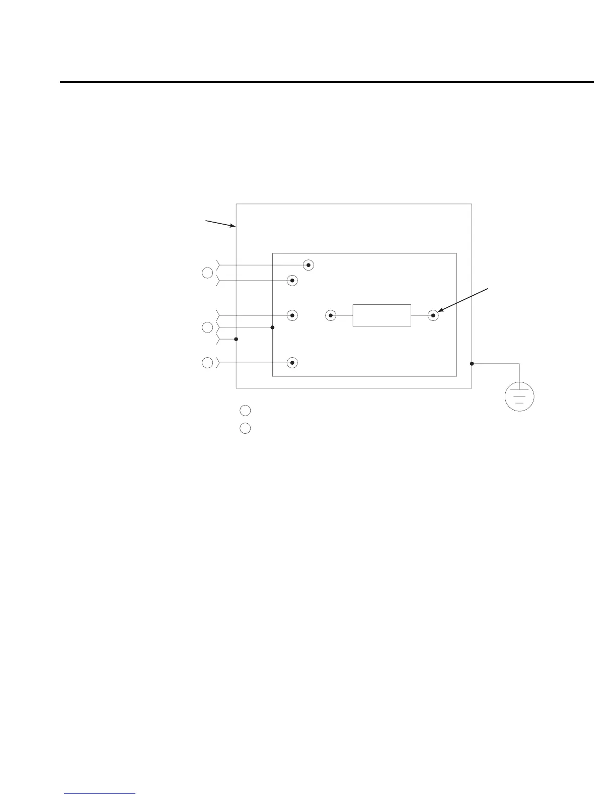
Test fixture
Whenever possible, use a shielded low leakage test fixture to make precision measurements.
A general purpose test fixture is shown in Figure 2-6. This test fixture will accommodate a vari-
ety of connection requirements.
Test fixture chassis
• The chassis of the test fixture should be metal so that it can function as a shield for the
DUT or test circuit. The metal chassis should be connected to chassis ground of Model
6514 via the triax cable.
• The test box must have a lid that closes to prevent contact with live circuitry.
• The test fixture must have a screw terminal that is used exclusively for connection to
safety earth ground.
WARNING To provide protection from shock hazards, the test fixture chassis must be
properly connected to safety earth ground. A grounding wire (#18 AWG or
larger) must be attached securely to the test fixture at a screw terminal
designed for safety grounding. The other end of the ground wire must be
attached to a known safety earth ground.
Guard plate
A metal guard plate will provide guarding or noise shielding for the DUT or test circuit. It
will also serve as a mounting panel for DUT or test circuits. The guard plate must be insulated
with 1000V spacing from the chassis of the test fixture.
Metal Chassis
To External
Source
To 6514
Input
To 6514
COMMON
Metal Guard Plate
Banana Jacks
3-Lug Female Triax Connector
Insulated
Terminal
Post (6)
Safety
Earth
Ground
A
A
A
B
B
DUT
Figure 2-6
General
purpose test
fixture