Calibration 19-17
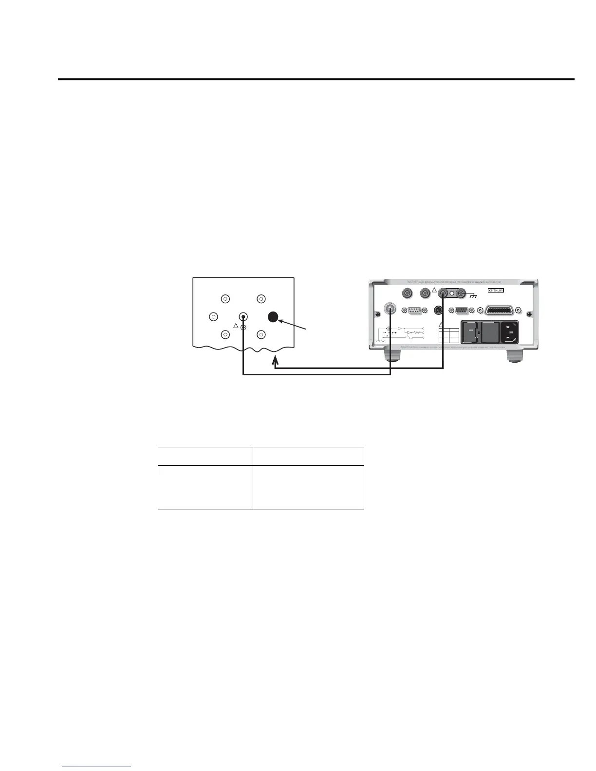
12. Disconnect the resistance calibrator, and connect the 1GΩ calibration standard resistor
to Model 6514 INPUT jack, as shown in Figure 19-6. Be sure to remove the link between
Model 5156 SHIELD and CHASSIS terminals. Also connect Model 5156 CHASSIS ter-
minal to Model 6514 COMMON jack.
WARNING Hazardous voltages may be present on Model 5156 SHIELD and OUTPUT
terminals.
13. Using the GRD key, enable Model 6514 guard mode.
14. Repeat steps 3 through 10 for the 2GΩ range. Be sure to set Model 6514 display to the
actual standard resistance value.
Table 19-7
Ohms calibration summary
Model 6514 range Calibration resistance*
2kΩ
∗∗
1.9kΩ
2MΩ 1.9MΩ
2GΩ 1GΩ
* Nominal values. Use actual values for calibration.
Use resistance calibrator for 2kΩ and 2MΩ ranges.
Use calibration standard resistor for 1GΩ range.
** Zero also calibrated on 2kΩ range.
RS232DIGITAL I/O
PREAMP
250V PK
2V
OUTPUT
COMMON CHASSIS
120
FUSE LINE
630mA
LINE RATING
50, 60Hz
60 VA MAX
T
(SB)
100 VAC
120 VAC
315mAT
(SB)
220 VAC
240 VAC
INPUT 250V PK
IEEE-488
(CHANGE IEEE
WITH FRONT PANEL MENU)
TRIGGER LINK
!
!
MADE IN
U.S.A.
V, GUARD
(PROGRAMMABLE)
OFF
ON
GUARD
(FOLLOWS
INPUT)
(INTERNAL)
INPUT PREAMP
10K
PREAMP
OUT
2V
OUTPUT
COM
To Shield
Model 6514 Electrometer
Triax Cable
100G
Ω
100M
Ω
10G
Ω
1G
Ω
1nF
100nF
OUTPUT
Model 5156 Calibration Standard
!
BNC shorting
cap
Remove SHIELD to CHASSIS link
Connect SHIELD to 6514 COMMON
Note: Enable guard mode.
gure
-
Connections for ohms
calibration (2G
Ω
range)