Status Structure 13-13
Operation event status
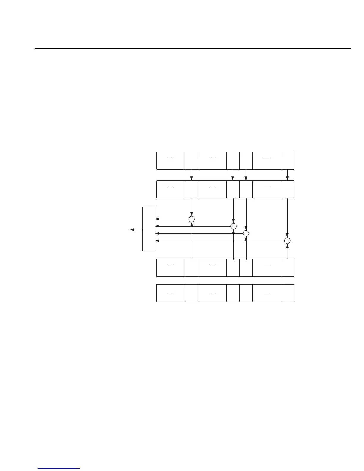
The used bits of the operation event register (shown in Figure 13-5) are described as follows:
• Bit B0, calibrating — Set bit indicates that Model 6514 is calibrating.
• Bit B5, waiting for trigger event (Trig) — Set bit indicates that Model 6514 is in the
trigger layer waiting for a TLINK trigger event to occur.
• Bit B6, waiting for arm event (Arm) — Set bit indicates that Model 6514 is in the arm
layer waiting for an arm event to occur.
• Bit B10, idle state (Idle) — Set bit indicates Model 6514 is in the idle state.
OR
Operation Event
Enable Register
Idle = In Idle
Trig = Waiting for trigger event
Arm = Waiting for arm event
Cal = Calibrating
& = Logical AND
OR = Logical OR
&
&
&
Cal
(B0)
&
1024
(2
10
)
32
(2
5
)
Decimal
Weights
OPC
(B0)
[:EVENt]?
64
(2
6
)
Cal
(B0)
(B4-B1)
Trig
(B5)
Arm
(B6)
Idle
(B10) (B9-B7)
(B15-B11)
:CONDition?
Trig
(B5)
Arm
(B6)
Idle
(B10) (B9-B7)
(B15-B11)
Operation Condition
Regiser
Operation Event
Regiser
(B4-B1)
Trig
(B5)
Arm
(B6)
Idle
(B10) (B9-B7)
(B15-B11)
1
(2
0
)
:ENABLe <NRf>
:ENABLe?
To OPC bit
of Status Byte
Register
(B4-B1)
Figure 13-5
Operation event
status