23
EN
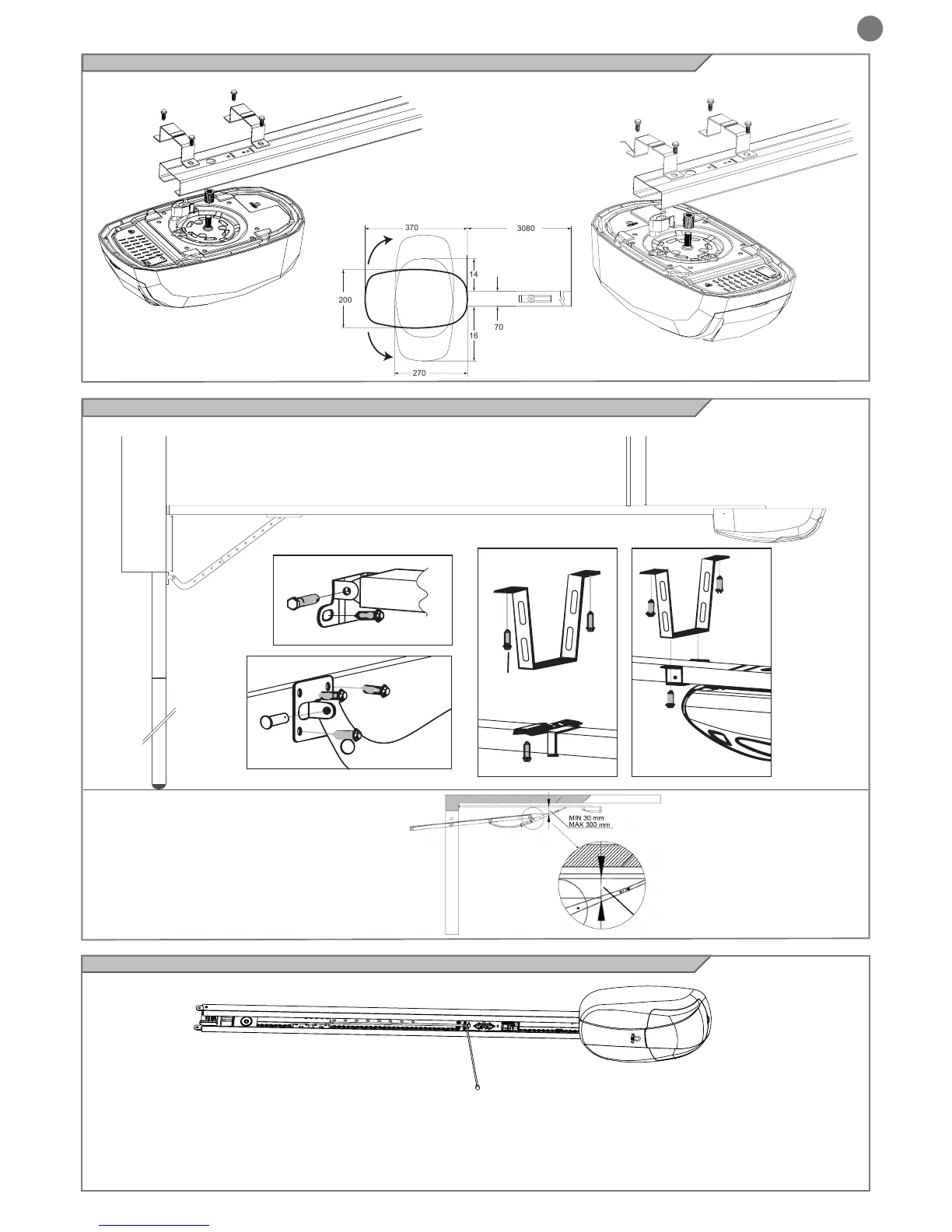
MIN 0 cm
MAX 40 cm
MAX 40 cm
Wall
Door
Support bracket
U bracket
Support bracket
6x80 Screw
Guide
Expansion plug
Expansion plug
Expansion
plug
8x25 Hinge pin
8x20 Screw
8x20 Screw
Curved arm for door
6x15 self-tapping
screw
Door bracket
Fastening
Fastening
with standard bracket included
4.2 Connection of the motor body to the guide
6x15 self tapping
screw
U bracket
Guide
lateral movement ring
90° rotated head
Standard
6x15 self tapping
screw
U bracket
Guide
lateral movement ring
4.4 Manual opening of door
Guide
Carriage
Cord
In case of power failure
(1). If the door is closed:
Pull the cord and release the clutch to allow the door to be lifted easily.
(2). If the door is open:
Pull the cord once to allow the door to lower to the closed position.
4.3 Installation of the guide and motor on the door
Position the guide with reference to gure
N.B. For installations on overhead doors, the
accessory BO-SEZ is required.
 Loading...