EN
24
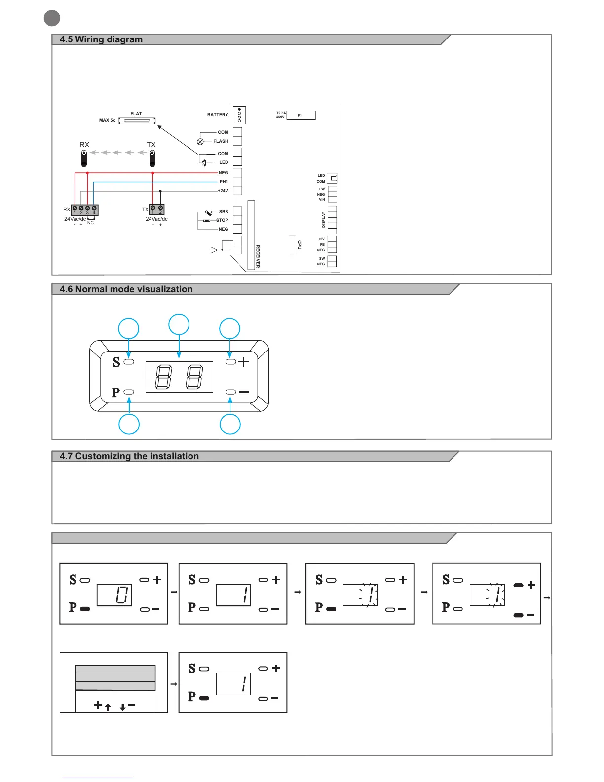
4.6 Normal mode visualization
In “NORMAL MODE”, when the installation is powered normally, the 2-digit LCD displays rotates and after 30 sec. will turn off
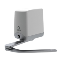
4.5 Wiring diagram
WARNING - Before making connections verify that the installation is not powered
The ashing light connection must be made between COM and FLASH
The external courtesy light connection must be made between COM and LED
The photocell contact must be made between PH1 and NEG (NC normally closed contact)
The emergency STOP contact must be connected between STOP and NEG (contact normally closed NC)
The step/step contact SBS must be connected between SBS and NEG (contact normally open NA)
4.7 Customizing the installation
Programming
Preparation A. Gently move the door to activate the carriage so that the automation system can guide the door
B. Power on. The light will turn on, the unit provides a single audible signal and the display indicates”0” in cycles.
Attention: If programming is not complete, the settings will be cancelled automatically. If incorrect information has been pro-
grammed, power off and then power back on, referring to the following.
4.8 Setting of opening limit
Press the key “P” for
5 seconds
Press”+”
Or press “-”
The unit emits 1 beep and “1”
is displayed
Door opening
Door closing
Press “P”, “1” ashes
When the door opens and
reaches the ideal position,
press the key “P” to save the
information.
Warning: the saved information has no effect if this procedure is used for setting the limit of closing
1
2
4
3
5
Description of the buttons
1 - P function button
2 - S memorization of remotes button
3 - + parameter increase button
4 - - parameters decrease button
5 - Display
 Loading...