EN
32
5.2 Commissioning
Following the successful testing of all (and not just some) devices in
the installation you can proceed with the commissioning
You must prepare, and keep for 10 years, the technical le of the
installation with the wiring diagram, drawing or photo of the installa-
tion, risks analysis and solutions adopted, manufacturer declaration
of conformity of all devices connected, instruction manual of each
device and maintenance schedule of the installation
Fix on the gate or door a plaque indicating the automation data, the
name of the person responsible for the commissioning, the serial
number and year of construction, the CE mark
Attach a plaque indicating the steps required to manually unlock
the motor
Implement and deliver to the end user the declaration of conform-
ity, the instructions and warnings for use for the end user and the
maintenance schedule of the installation
Make sure the user understands properly the automatic, manual
and emergency operation of the automation.
Inform the end user in writing of the dangers and risks still present
WARNING - after detecting an obstacles, the gate or door stops,
and the automatic closing is excluded; to restore movement
you must press the command button or use the transmitter.
5 - TESTING AND COMMISSIONING THE AUTOMATION
5.1 Testing
All installation components must be tested following the procedures
outlined in the respective instruction manuals
Check that they meet the guidelines in Chapter 1 - Safety warnings
Check that the gate or door can move freely once the automation
is unlocked, and that they are balanced and stationary if left in any
position
Check the correct operation of all connected devices (photocells,
sensitive edges, emergency buttons, etc.), testing the opening,
closing and stopping of the gate or door via the connected control
devices (transmitters, buttons, switches)
Carry out measurements of the impact force, as prescribed by
standard EN12445 adjusting the functions of speed, motor force
and deceleration of the unit if the measurements do not give the
desired results until you nd the right setting
The testing of the automation must be performed by qualied tech-
nicians who must perform the tests required by relevant legisla-
tion related to risks, ensuring compliance with the provisions of the
regulations, in particular the EN12445 standard, which species the
testing methods for the automation of doors and gates.
6 - INSIGHTS
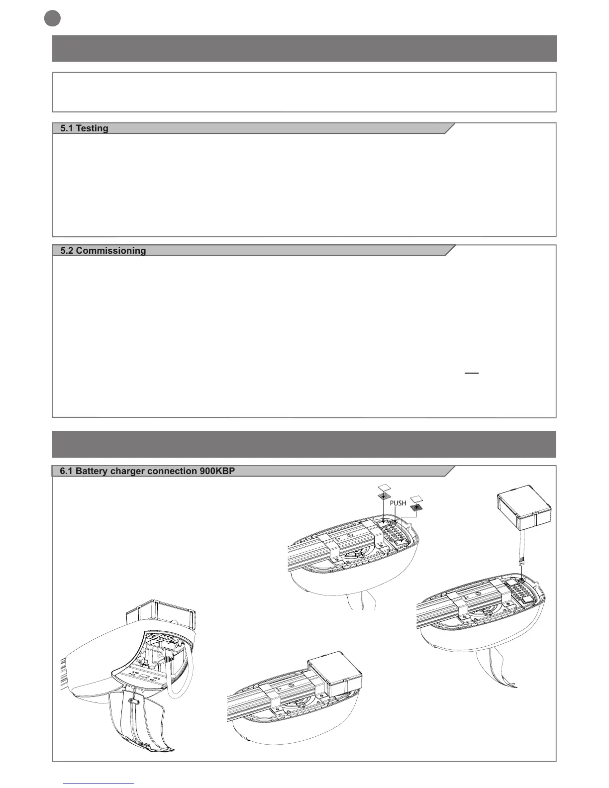
6.1 Battery charger connection 900KBP
VIPER LED can also function in the absence of main power supply
by installing 900KBP without making any modications to the system.
Connection sequence:
• Disconnect the 230 VAC power supply (120 Vac)
• Connect the 900KBP module as shown in the gure
• Re-connect the mains power supply
• New batteries charge up after about ten hours
Fig.1
Fig.2
Fig.3
Fig.4
 Loading...