Setting Up the Oscilloscope 1
Infiniium Z-Series Oscilloscopes User’s Guide 21
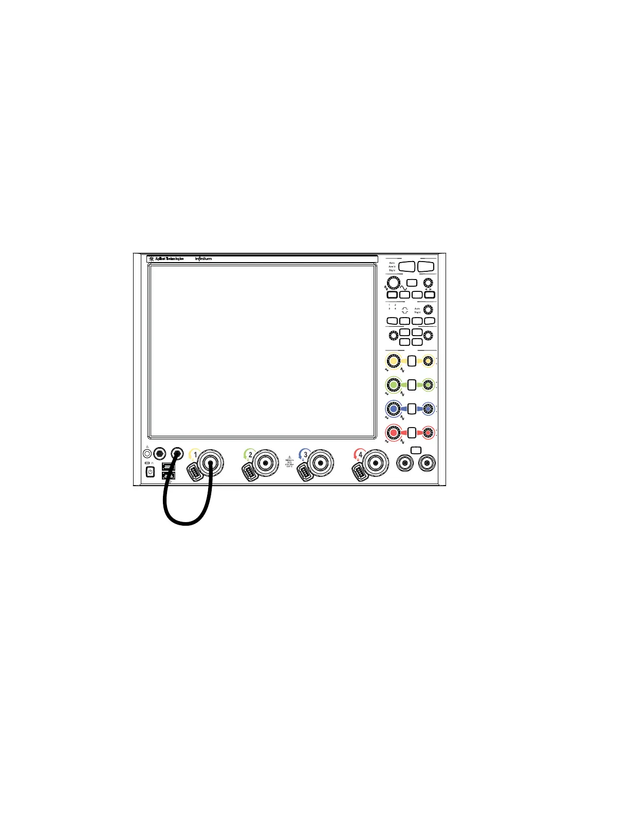
Verifying Basic Oscilloscope Operation
1 Install the supplied connector savers to each channel input. Keysight
recommends using the connector savers to protect the input connectors.
2 Connect one end of the 54916-61626 calibration cable to oscilloscope input
channel 1.
3 Connect the other end of the calibration cable to the Cal Out connector on the
front panel.
4 Press [Default Setup] on the front panel.
The display will pause momentarily while the oscilloscope is configured to its
default settings.
5 Press [Auto Scale] on the front panel.
The display will pause momentarily while the oscilloscope adjusts the time/div
setting and vertical scale. You should then see a square wave with about four
cycles on screen and a peak-to-peak amplitude of approximately five divisions.
Figure 6 Verifying Basic Oscilloscope Operation
1R 3R
Aux
Run Control
Horizontal
Level
Trigger
Measure
Vertical
Position Touch Turn
Aux Out Cal Out
for Vernier
Push
Push
to Zero
Push
for Vernier
Push
to Zero
Push
(Push for 50%)
for Vernier
(Push to Toggle)
(Hold to Reset)
to Zero
Push
Menu
Source
Slope Sweep
Auto
Scale
Default
Setup
Clear
Display
Multi
Purpose
1
2
3
4
Run
Stop
Single
Print
Screen
Zoom
Touch
Short
Cut
Markers
RealEdge
Digital Storage OscilloscopeDSO-X 96204Q 160 GSa/s62 GHz
Calibration Cable (54916-61626)
Digital Storage Oscilloscope
Digital Storage Oscilloscope
DSO-Z 204A
80 GSa/s
20 GHz
Z-Series
 Loading...