Using the Oscilloscope 2
Infiniium Z-Series Oscilloscopes User’s Guide 29
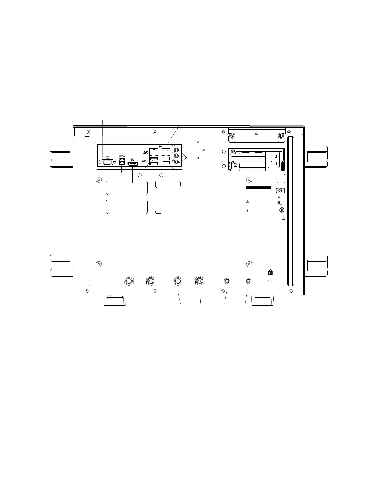
Back Panel Inputs and Outputs
The Infiniium Z-Series oscilloscope’s back panel has the motherboard I/O
connectors and reference clock synchronization connectors.
Motherboard I/O
The motherboard provides these inputs/outputs/ports in the oscilloscope: four
USB ports for peripherals, an external monitor connector, USB III device port (for
remote control of the oscilloscope from a PC), LAN port, and speaker and
microphone connectors.
10 MHz In, 10 MHz Out
The 10 MHz In BNC connector is used to synchronize the oscilloscope's horizontal
timebase system to a reference clock that you provide. The clock that you provide
must meet the following specifications:
Figure 9 Infiniium Z-Series Oscilloscope Back Panel I/O
Reference clock synchronization connectors
Audio connectors
CAUTION: Power down
instrument before
insertion or removal
of hard drive.
Removable
Hard Drive
N10149
~ Line
1350W Max
100 - 240V
50/60 Hz
10 MHz inTrig Out 10 MHz out 100 MHz in 100 MHz out
CAUTION: Use only with
power cable specified by
owner’s guide.
WARNING: Maintain
ground to avoid electric
shock.
Aux Trig
169323
Device
NOTICE
Well-regulated power
required for 100-120V
operation.
USB III host ports
LAN connector
External monitor
connector
USB III
Device port
Display port
USB host ports