26 Infiniium Z-Series Oscilloscopes User’s Guide
2 Using the Oscilloscope
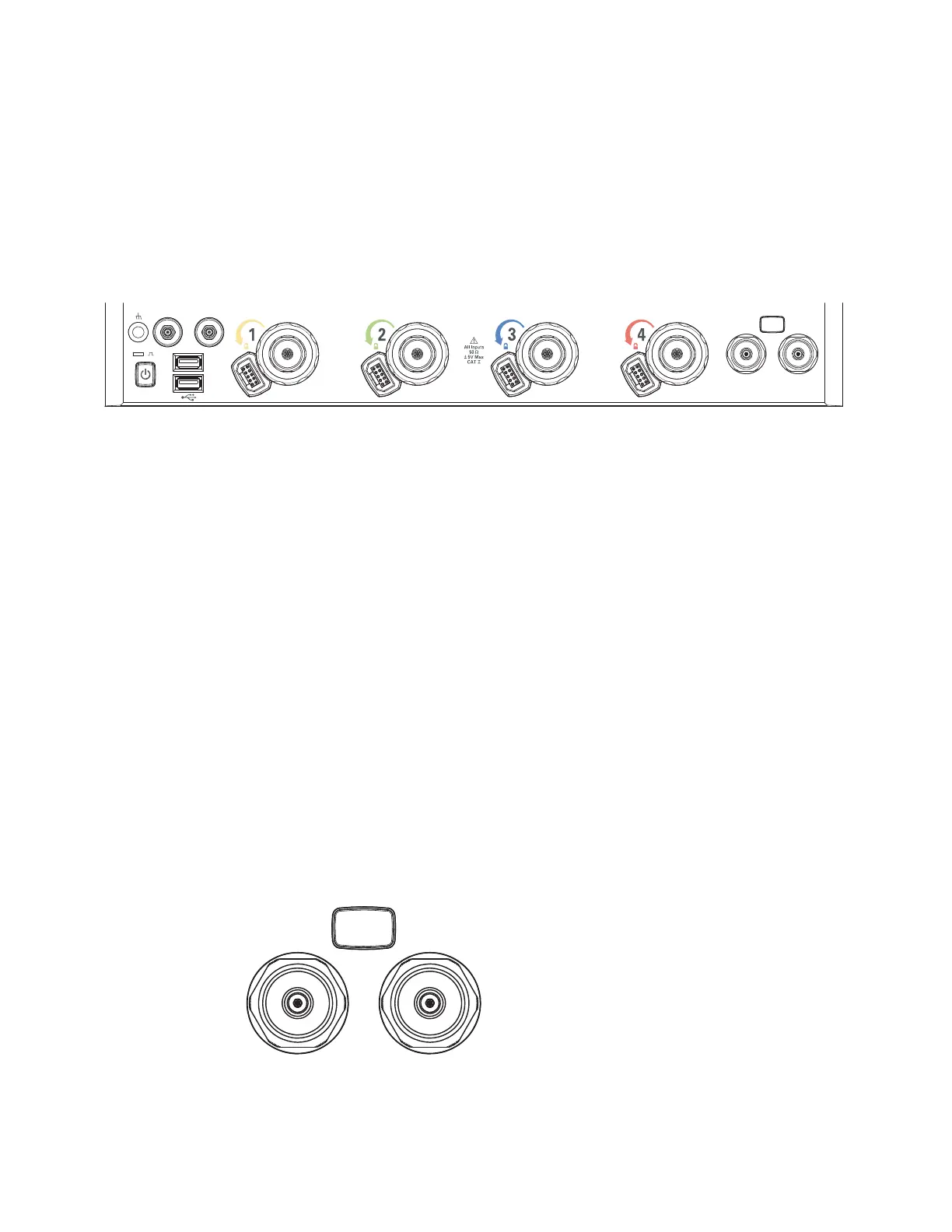
Front Panel Inputs and Outputs
On the Infiniium Z-Series oscilloscopes, the channel inputs and the Aux Out and
Cal Out outputs appear on the lower part of the front panel. The ground plug, probe
compensation terminal, and two USB host ports are also located here.
Channel 1-4 Inputs
The channel 1-4 inputs have:
• 3.5 mm threaded RF connectors
• A convenient automatic torque mechanism
• An AutoProbe II interface connector with pins that provide probe power,
identification, and other communication signals
The AutoProbe II interface works with the InfiniiMax III probing system. See
“Connecting Oscilloscope Probes" on page 17.
You can also connect 3.5 mm threaded RF cables to the channel 1-4 inputs.
RealEdge 1R, 3R Channel Inputs
The [RealEdge] key and 1R and 3R channel inputs appear on 50 GHz and 63 GHz
bandwidth models.
Pressing the [RealEdge] key enables or disables the RealEdge 1R and 3R channel
inputs. The [RealEdge] key is lit when enabled.
Figure 7 Infiniium Z-Series Oscilloscope Front Panel I/O
1R 3R
Aux Out Cal Out
RealEdge
Figure 8 RealEdge Channel Inputs and [RealEdge] Key