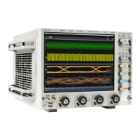
Using the Oscilloscope 2
Infiniium Z-Series Oscilloscopes User’s Guide 27
When enabled, the RealEdge 1R and 3R channel inputs take over the standard
channels 1-4, except for the trigger circuitry on channels 2 and 4. When RealEdge
is enabled, you can still trigger on signals connected to the channel 2 and 4 inputs
(but you cannot capture or display data from these signals).
You can connect 1.85 mm threaded RF cables to the RealEdge 1R and 3R channel
inputs.
Ground
The ground plug is convenient for ESD wrist straps.
Aux Out
This output signal is selected by the Infiniium oscilloscope application's
Calibration Output dialog box (Utilities > Calibration Output...). It can be a DC level,
the probe compensation signal (a square wave used to adjust compensated
passive probes), the trigger out signal, or a demo signal.
Cal Out
This calibration output is used when performing a user calibration on the
oscilloscope.
A calibration cable is included with the oscilloscope. The 50 GHz and 63 GHz
bandwidth models include a second calibration cable for the RealEdge channel
inputs.
You can also use the Infiniium oscilloscope application’s Calibration Output dialog
box (Utilities > Calibration Output...) to select other output signals, just like you can
for the Aux Out output.
Probe Compensation Terminal
This terminal has a square wave signal that is used to adjust compensated passive
probes.
You can also output a DC level on this terminal using the Infiniium oscilloscope
application's Calibration Output dialog box.
USB Host Ports
Two USB host ports are located on the front panel, next to the power switch, for
connecting peripherals.