General Information
P/N 06-236716-001 1-5 August 2007
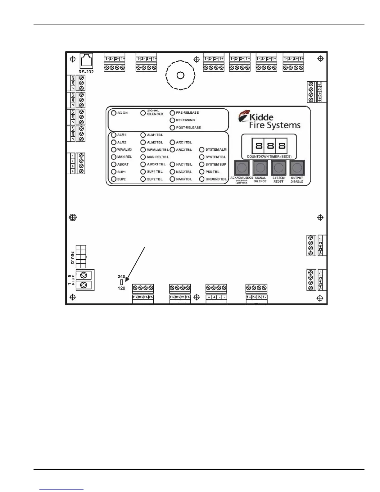
Figure 1-2. Printed Circuit Board (PCB)
1-4.3.1 OPERATOR INTERFACE
All alarms, troubles and supervisory signals are received at the control unit and displayed for
the operator. The Operator Interface consists of four main components and are visible and/or
audible through a transparent window:
•LED Indicators
•Control Switches
• Digital Display
• Buzzer
TB1
TB2
TB3TB4
TB5
TB6
TB7
TB8
TB9
TB10
TB11
TB12
TB17
TB16TB15
TB14
TB19
TB18
TB13
DETECTOR 1
DETECTOR 2
WATERFLOW/
DETECTOR 3
MANUAL
RELEASE
ABORT
SUPERVISORY
1
SUPERVISORY
2
TROUBLE
RELAY 3
RELAY 2
RELAY 1
BATT OUT
AC IN
RELEASE 1
ARC 1
RELEASE 2
ARC 2
AUX
24 VDC
NAC 3
NAC 2
NAC 1
AC SUPPLY SELECT SWITCH (S6)
 Loading...
