Installation
P/N 06-236716-001 2-9 August 2007
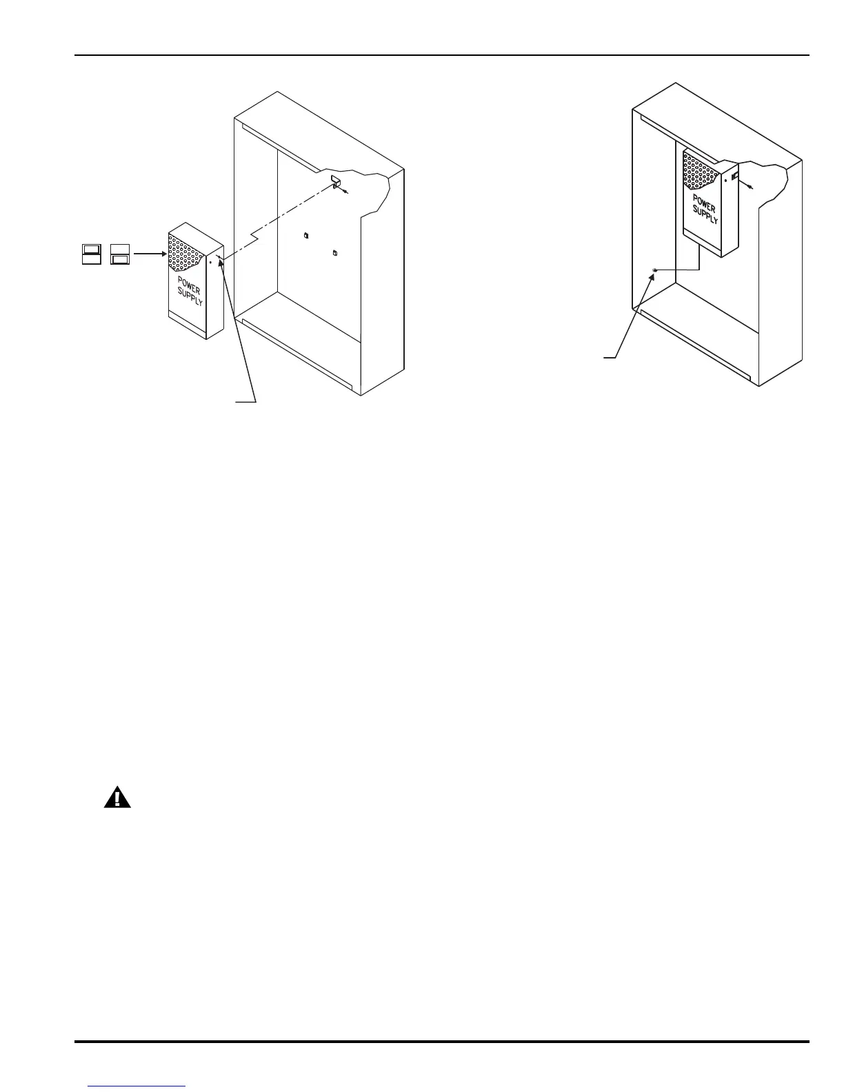
Figure 2-7. Power Supply Unit Installation
5. Thread the supplied 3 x 10 mounting screw part way into the lower of the two threaded
holes of the power supply unit. See Figure 2-7.
6. Set the power supply unit AC-input-voltage selector switch to either 115 Vac or 230 Vac.
Use the 115 Vac position for 110-120 Vac supplies and 230 V position for 230-240 Vac
supplies. See Figure 2-7.
7. Locate the two power supply unit retention tabs and the fastening tab in the
enclosure’s back panel.
8. Position the power supply unit with the wire harness down, and then slide it onto the retention
tabs. The 3 x 10 mm mounting screw should slide into the slot of the fastening tab at the same
time.
9. Tighten the screw onto the fastening tab.
10.Connect the ring end of the power supply’s green ground wire (P/N 06-129928-002) to the
earth-ground stud on the lower left side of the backbox wall. See Figure 2-6 and
Figure 2-7.
2-3.3 Installing the Printed Circuit Board (PCB), P/N 06-220113-001
1. Make sure the control unit location is dry and that the enclosure is free of construction dust
and metal shavings prior to installing the PCB.
CAUTION
Use a ground strap to prevent static discharge that could damage sensitive
components on the Printed Control Board.
RETENTION
TABS
TYP (2)
FASTENING TAB
FOR SCREW
THREADED HOLE FOR
3 x 10 mm MOUNTING
SCREW
GROUND WIRE ATTACHED
TO GROUND STUD
115 V
230 V
 Loading...
