Installation
P/N 06-236716-001 2-23 August 2007
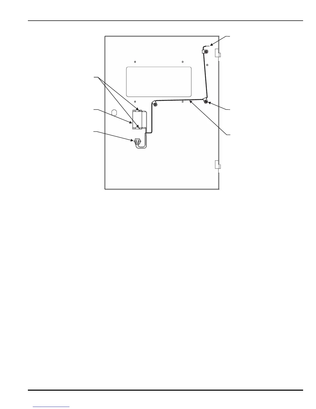
Figure 2-18. Installing Switch Harness Assembly
2-9 COMPLETING THE INSTALLATION
1. Power-up the system AC first and then DC.
2. Configure as described in Chapter 3.
3. Once configured, test the complete system for operation. Once operation is verified, the
installation is complete.
CABLE CLAMP
AND 8-32 KEP NUT
(SUPPLIED)
(TYP 3 PLACES)
SWITCH WIRE
HARNESS
ABORT
SWITCH
MANUAL
RELEASE
SWITCH
- WHITE WIRES
TO TB5
- BLACK WIRES
TO TB4
BLACK WIRES
FROM SWITCH
WIRE HARNESS
REAR VIEW
 Loading...
