Installation
August 2007 2-14 P/N 06-236716-001
2-4 TERMINATIONS AND WIRING DIAGRAMS
2-4.1 Terminal Blocks
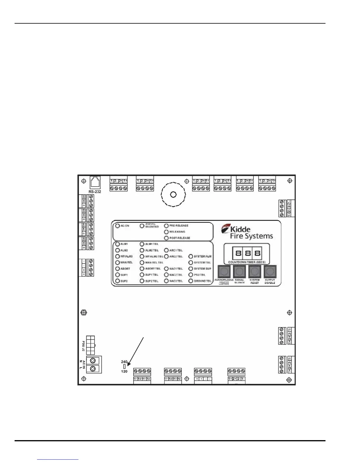
The PCB provides the following input and output terminations as shown in Figure 2-12.
Figure 2-12. Printed Circuit Board
• Detector 1 (TB1) • Trouble Relay (TB8) • Agent Release ARC 2 (TB15)
• Detector 2 (TB2) • Programmable Relay 3 (TB9) • Aux 24 Vdc Output (TB16)
• Waterflow/Detector 3 (TB3) • Programmable Relay 2 (TB10) • Notification Appliance Circuit 3 (TB17)
• Manual Release (TB4) • Programmable Relay 1 (TB11) • Notification Appliance Circuit 2 (TB18)
• Abort (TB5) • Battery Out (TB12) • Notification Appliance Circuit 1 (TB19)
• Supervisory 1 (TB6) • AC IN (TB13) • PSU (J2)
• Supervisory 2 (TB7) • Agent Release ARC 1 (TB14) • RS-232 Communications Port
TB1
TB2
TB3TB4
TB5
TB6
TB7
TB8
TB9
TB10
TB11
TB12
TB17
TB16TB15
TB14
TB19
TB18
TB13
DETECTOR 1
DETECTOR 2
WATERFLOW/
DETECTOR 3
MANUAL
RELEASE
ABORT
SUPERVISORY
1
SUPERVISORY
2
TROUBLE RELAY
PROGRAMMABLE RELAY 3
PROGRAMMABLE RELAY 2
PROGRAMMABLE RELAY 1
BATT OUT
AC IN
RELEASE
ARC 1
RELEASE
ARC 2
AUX
24 VDC
NAC 3
NAC 2
NAC 1
AC SUPPLY SELECT SWITCH (S6)
 Loading...
