Installation
August 2007 2-22 P/N 06-236716-001
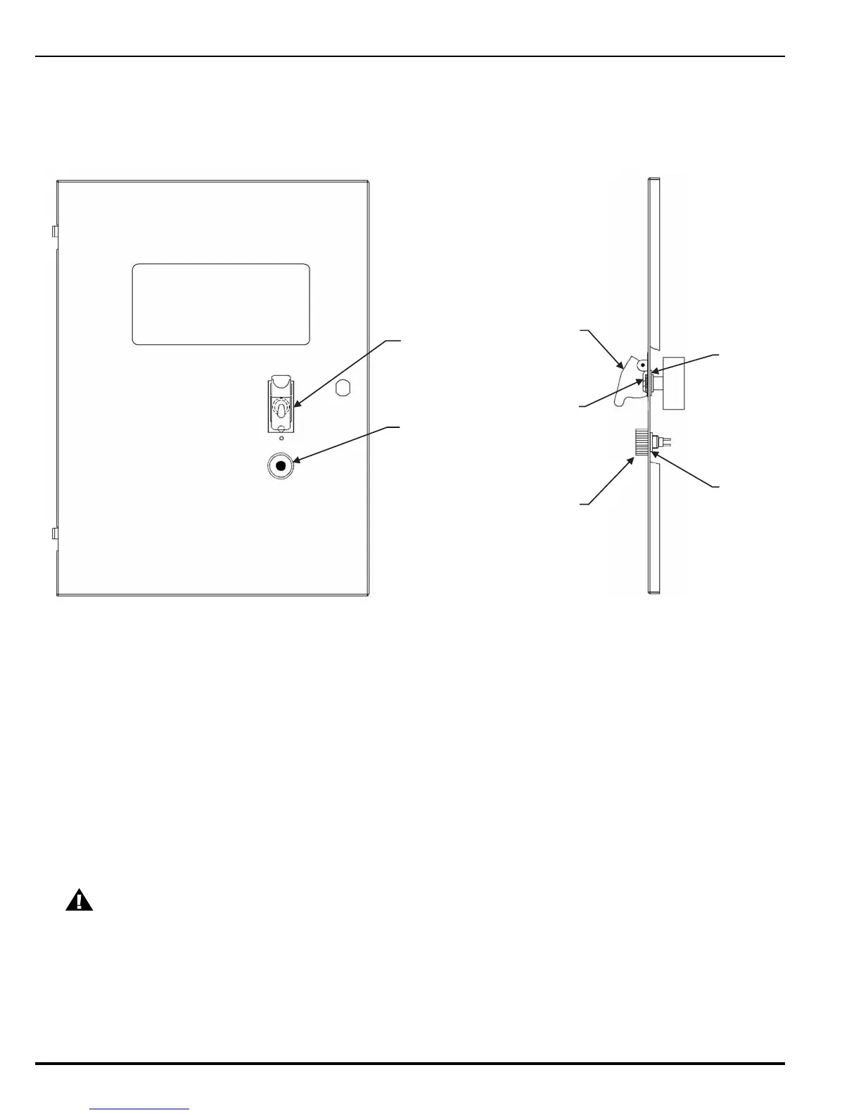
Note: Switch guard is keyed and can only be installed one way.
4. Install locking nut on the abort switch.
5. Install abort switch from back of enclosure door. Attach pushbutton switch guard and
tighten.
Figure 2-17. Installation of Manual Release and Abort Switches
6. Attach black wires from switch wire harness to the right side of the toggle switch as shown
in Figure 2-18.
7. Route switch wire harness as shown in Figure 2-18.
8. Install cable clamps and 8-32 kep nuts to secure switch wire harness to enclosure door.
9. Run the black wires from the Manual Release switch to TB4 on the PCB. Refer to
Figure 2-13 through Figure 2-15 for wiring configurations.
10. Run the white wires from the Abort switch to TB5 on the PCB. Refer to Figure 2-13 through
Figure 2-15 for wiring configurations.
CAUTION
Power-limited wiring from the front cover Manual Release and Abort switches
to their respective terminal blocks on the PCB must be routed to maintain a
1/4-inch distance from non-power-limited wiring. Refer to Appendix F for more
details.
FRONT VIEW
SIDE VIEW
MANUAL
RELEASE
SWITCH
ABORT
SWITCH
PUSHBUTTON
SWITCH
GUARD
SWITCH
GUARD
INTERNAL
TOOTH
LOCKWASHER
AND LOCKING RING
LOCKING
NUT
LOCKING
NUT
MANUAL RELEASE
ABORT
 Loading...
