Installation
August 2007 2-4 P/N 06-236716-001
2-3 INSTALLATION PROCEDURE
2-3.1 Mounting the Enclosure Assembly, P/N 06-220132-001
The control unit is designed to be surface or semi-flush mounted. Use screws or bolts no
smaller than No. 10 (3/16-inch or 5 mm) in diameter to secure the enclosure to wall studs or
masonry walls. Never mount the enclosure to drywall or plaster walls without securing to studs.
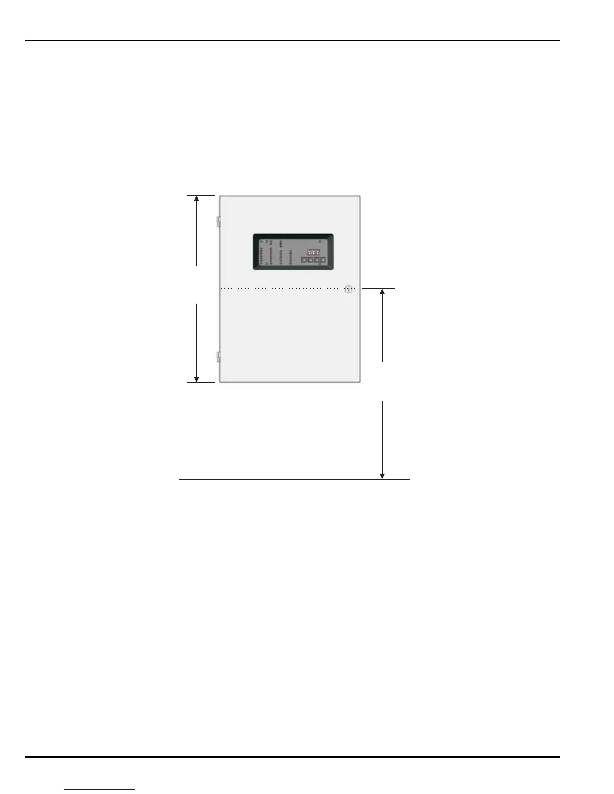
Locate the middle of the enclosure approximately 66-inches (1676 mm) above the floor so the
control unit display is positioned at a convenient height for the operator. Refer to Figure 2-1.
Figure 2-2 shows the control unit enclosure dimensions.
Figure 2-1. Installation Height Above Floor
Perform the following steps prior to installing the enclosure:
1. Disconnect the ground wire that connects the enclosure door to the back box.
2. Remove the control unit front door by rotating the door approximately 90° from its closed
position. Lift up the door to allow the door’s hinge pins to clear the mating-hinge sockets
on the back box.
3. Remove the separately packaged power supply, printed-circuit board, and installation kit,
and set them and the front door aside in a safe location to prevent damage.
19 in.
(483 mm)
66 in.
(1676 mm)
MAX.
FLOOR
 Loading...
