Installation
August 2007 2-12 P/N 06-236716-001
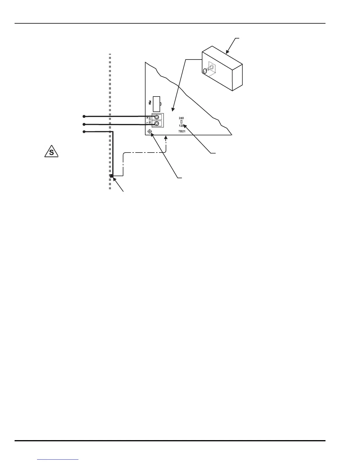
Figure 2-10. Primary Power Connections
4. To install the Protective Cover for AC Power input, fold along scored lines as shown in
Figure 2-10.
5. Insert spacer and align thru holes and spacer with PCB standoff in lower left corner.
6. Attach to PCB with nylon screw.
ENCLOSURE WALL
WHITE (NEUTRAL)
BLACK (LINE/HOT)
GREEN (GREEN)
POWER CONNECTIONS
FROM AC SUPPLY
LOWER LEFT CORNER OF
PRINTED CONTROL BOARD
AC POWER SELECTION SLIDE SWIT
DOWN FOR 120 Vac / UP FOR 220-240
STANDOFF FOR AC PROTECTIVE COVER
PROTECTIVE COVER
FOR AC POWER INPUT
TB13
TO PSU
EARTH GND
SUPERVISED
 Loading...
