General Information
August 2007 1-6 P/N 06-236716-001
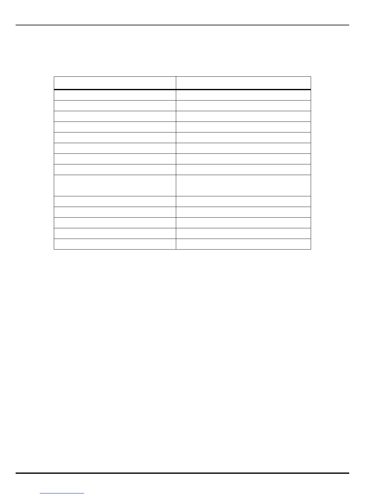
1-4.3.1.1 LED Indicators
The following is a list of control unit indicators and their LED display color.
1-4.3.1.2 Control Switches
There are four Control Switches on the Operator Interface. They are:
• Acknowledge — Silences the buzzer which sounds when a new supervisory, alarm, or
trouble is detected. Holding this control switch for five seconds, activates the control unit
Lamp Test. This control switch is also used in conjunction with the System Reset control
switch to enter the configuration mode.
Note: Microprocessor and PCB troubles are latching and cannot be silenced or reset. Refer to
Chapter 6, Troubleshooting.
• Signal Silence — Silences the NAC circuits.
• System Reset — Disconnects power from all input and output circuits and the auxiliary
output for a period of five (5) seconds. This control switch is also used in conjunction with
the Acknowledge control switch to enter the configuration mode.
• Output Disable — Disables the release of agent, and as selected in the system
configuration, the activation of NAC outputs and/or Programmable Relays. This is used
when performing maintenance on the system.
Table 1-3. LED Indicator and Display Color
Indicator Display Color
AC Power On Green
System Alarm Red
System Supervisory Yellow
System Trouble Yellow
Signal Silenced Yellow
Agent Pre-Release Red
Agent Releasing Red
Agent Post-Release Red
Input Activated Alarm, Manual Release, and Abort — Red
Other — Yellow
Input Trouble Yellow
Release Output Trouble Yellow
NAC Output Trouble Yellow
Ground Fault Yellow
Power Supply Fault Yellow
 Loading...
