Installation
P/N 06-236716-001 2-5 August 2007
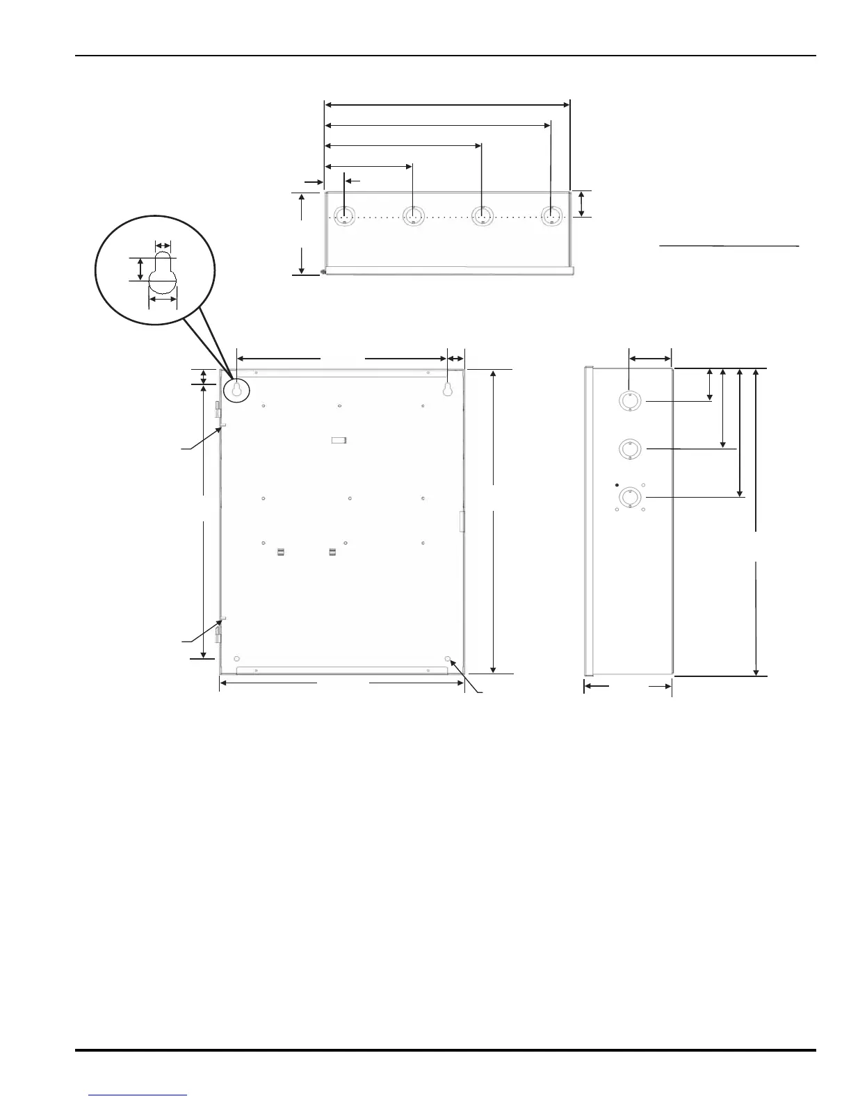
Figure 2-2. Control Unit and Surface Mounting Dimensions
2-3.1.1 SURFACE MOUNTING
1. Mark and pre-drill holes for four mounting bolts using the dimensions shown in Figure 2-2.
The installer must supply the mounting bolts (No. 10 or 3/16-inch (5mm)). There are two
holes and two keyhole slots in the backbox that serve as a template for surface mounting.
The type of hardware to be used is at the discretion of the installer, but must be installed
in accordance with NFPA 70 (NEC).
2. Insert the upper two fasteners in the wall. Leave approximately 1/4-inch (6 mm)
protruding for both screws.
3. Slip upper keyholes of the back box over the two protruding screws. Tighten the screws.
4. Insert and tighten the two lower screws.
5. Attach wiring conduit to the enclosure via the enclosure knockouts, and pull the required
number of wires through the conduit to the enclosure. Leave approximately 2 to 3 feet (600
to 900 mm) of wire length in the enclosure for future internal connections.
1-1/8 in.
(29 mm)
5-1/8 in.
(130 mm)
9-1/8 in.
(232 mm)
13-1/8 in.
(333 mm)
14-1/4 in.
(362 mm)
1-1/2 in.
(38 mm)
5 in.
(127 mm)
5 in.
(127 mm)
2 in.
(57 mm)
5 in.
(127 mm)
8 in.
(203 mm)
19 in.
(483 mm)
2-1/2 in.
(64 mm)
12-1/4 in.
(311 mm)
1 in.
(25 mm)
1 in.
(25 mm)
18-13/16 in.
(978 mm)
17 in.
(432 mm)
14-3/16 in.
(360 mm)
1/2 in.
(13 mm)
9/32 in.
(7 mm)
7/16 in.
(11 mm)
TYP 2 PLACES
TOP VIEW
SIDE VIEW
FRONT VIEW
GROUND
STUD
GROUND
STUD
1-1/2 in. (38 mm) KNOCKOUTS
4ONTOP
3 ON EACH SIDE
1 ON BOTTOM
9/32 in. DIAMETER
HOLES TYP (2)
PLACES
 Loading...
