Battery Capacity Calculations
P/N 06-236716-001 A-1 August 2007
APPENDIX A
BATTERY CAPACITY CALCULATIONS
A-1 STANDBY TIME DURATION
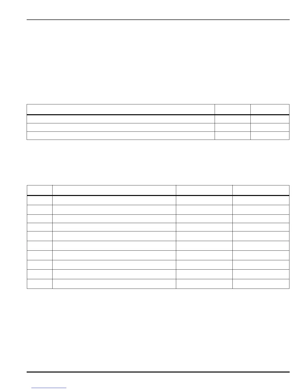
To calculate battery capacity for a specific application, first select the duration for which
standby and alarm power is required using Table A-1.
A-2 POWER CONSUMPTION DATA
Table A-2 lists the power consumption of the various system components.
1
The standby and alarm values for the AEGIS include the Trouble Relay.
2
The Auxiliary Power Output current value stated is the maximum allowed.
3
The Standby current stated for Ionization, Photoelectric, Electronic Heat, Duct and Contact Heat Detectors is
for each detector. The Alarm current is for the Detection Circuit.
4
The current value stated for the Notification Appliance Circuits is the maximum each.
5
For the Alarm current values of Steady Release Solenoids, refer to Appendix B.
6
Momentary Agent Release Solenoids and Initiators are negligible in their current requirements and do not
need to be included in the calculation.
Table A-1. Duration Time for Standby and Alarm
Type of System Standby Alarm
Local or Central Station (Protected Premises) Fire Alarm Systems per NFPA 72 24 hours 5 minutes
Clean Agent Suppression Systems per NFPA 12, 12A, 12B, and 2001 24 hours 5 minutes
Deluge or Pre-Action Water Spray Systems per Factory Mutual 90 hours 10 minutes
Table A-2. Power Consumptions for System Components
Number Component Standby Power (mA) Alarm Power (mA)
1
Kidde AEGIS™ Control Unit
1
100.00 240.00
2
Auxiliary Power Output
2
1000.00 Max. 1000.00 Max.
3 Programmable Relays 0.00 20.00
4 Ionization/Photoelectric/Electronic Heat Detectors 0.07 70.00
5
DH-60 (2W) Duct Detectors
3
0.07 70.00
6
Contact Type Heat Detectors
3
0.00 70.00
7
NACs 1, 2, and 3
4
0.00 1500.00 each
8
Release Solenoids - Steady
5
0.00 Refer to Appendix B
9
Release Solenoids - Momentary
6
0.00 0.00
10
Release - Initiators
6
0.00 0.00
 Loading...
