Installation
August 2007 2-20 P/N 06-236716-001
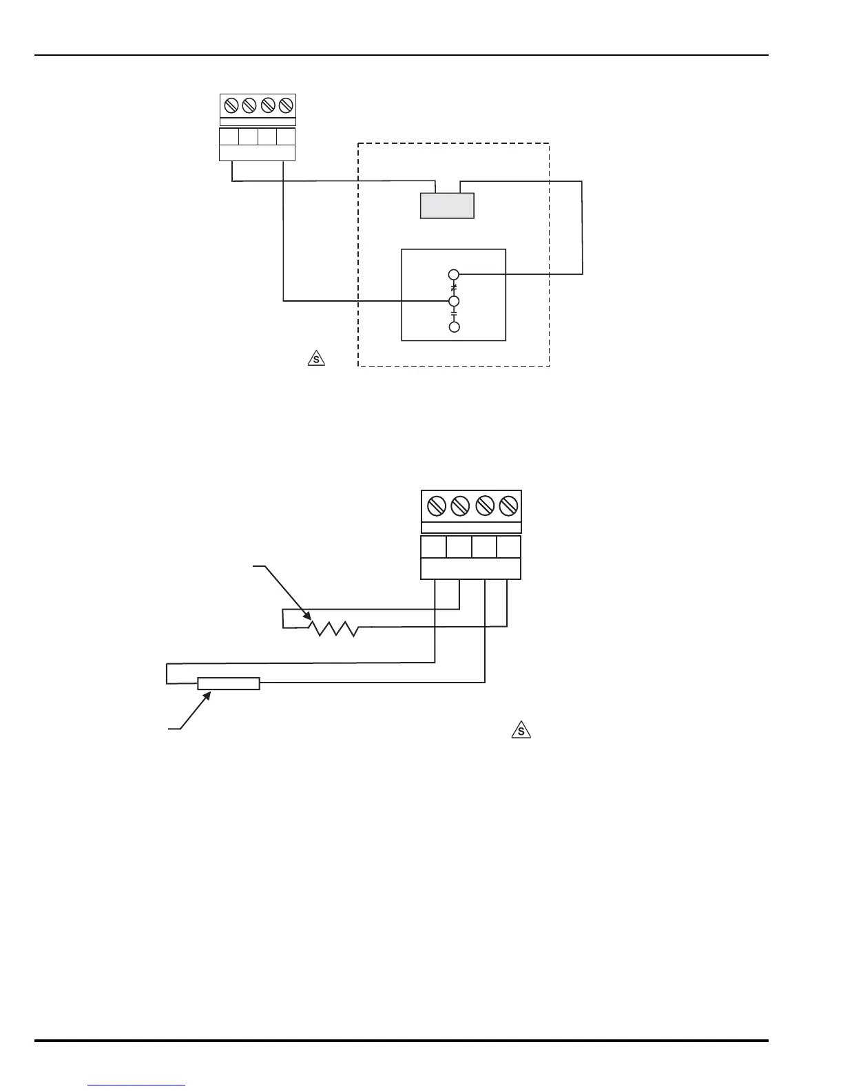
Figure 2-15E. Agent Release Circuit for XV and CXV Control Heads
Figure 2-15F. Agent Release Circuit - Initiators, Non-Power-Limited
Note: 1. Polarities must be observed for solenoids P/N 890181 and 48650001.
2. The inline releasing device P/N 06-220023-001 must be close nippled
to Solenoid enclosures.
3. The ARC is Non-Power-Limited when in-line device is not used.
4. Route Non-Powered-Limited wiring at least 1/4-inch away from all Power-Limited
wiring. See Appendix F. Do not attach Power-Limited wiring to the same
terminal block.
5. When firing initiators, the limiting resistor must have a rating of 1 watt minimum.
6. Control Head P/N 90-487100-001 when used with the control unit must
include Solenoid P/N 83-100034-001 and Microswitch P/N 87-120039-001.
Figure 2-15. Agent Release Circuit Wiring
WHITE
N.O.
N.C.
BLACK
SOLENOID P/N 83-100034-001
MICROSWITCH P/N 87-120039-001
TB14 OR TB15
R1+
R1-
R2-
R2+
NOTE
TO MAKE THIS A POWER LIMITED CIRCUIT, ADD IN-LINE RELEASING
DEVICES (P/N 06-220023-001) AS SHOWN IN FIGURE 2-15C.
TB14 OR TB15
10 OHM LIMITING
RESISTOR
MAXIMUM WIRE RESISTANCE: 3 OHMS
R1+
R1-
R2-
R2+
MAXIMUM CURRENT UNDER
FAULT CONDITIONS: 5A
INITIATOR
 Loading...
