Installation
August 2007 2-10 P/N 06-236716-001
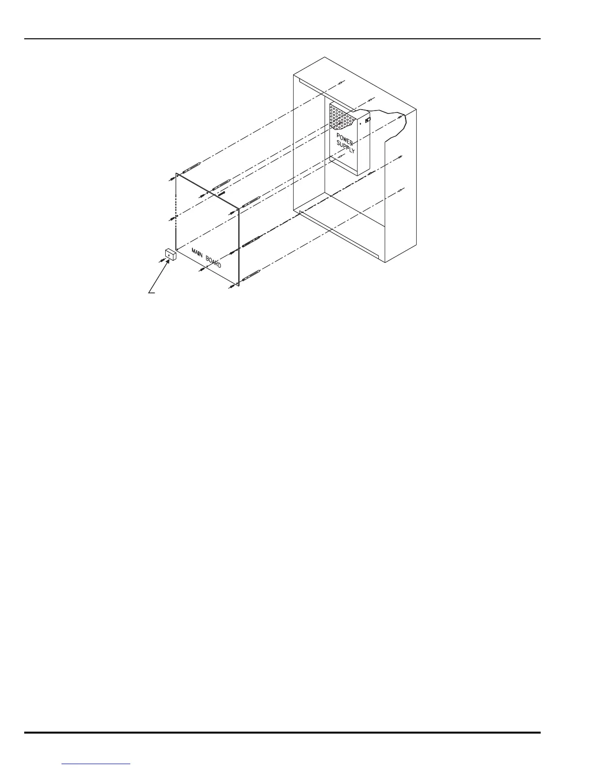
Figure 2-8. PCB Installation
2. Securely screw one each of the eight (8) 2-3/8 inch (60 mm) aluminum standoffs
(P/N 06-118533-001) onto each of the eight (8) threaded PEMs on enclosure backbox (top
three rows) as shown in Figure 2-8.
Note: Do not use the bottom row of threaded PEMs.
3. Slip on a wrist ground strap and clip the ground strap to the earth ground in the enclosure.
Do not remove the PCB from its shipping carton unless you have established a common
earth-ground potential among yourself, the enclosure, and the PCB shipping carton.
4. Remove the PCB from its shipping carton and position each of its eight (8) mounting holes
over one of the aluminum standoffs so that the AC-input terminal block is in the lower-left
corner.
5. Secure the PCB to the standoffs using the seven (7) 8-32 x 5/16 (8 mm) (P/N 06-250354-
082). Do not tighten the screws at this time.
The PCB mounting hole in the lower left corner utilizes a longer nylon screw that also holds
the AC Safety Cover in place. See Paragraph 2-3.4.1.
6. Place the free end of the longer of the two factory-installed Earth-Ground wires under the
screw assembly of the PCB (marked detail A in Figure 2-9). Tighten the remaining eight
screws. Be careful not to over-tighten.
7. Plug the harness from the power-supply unit into Connector J2 in the lower-left-hand
corner of the PCB.
AC PROTECTIVE COVER
(WITH STANDOFF)
 Loading...
