Troubleshooting
P/N 06-236716-001 6-1 August 2007
CHAPTER 6
TROUBLESHOOTING
6-1 PURPOSE
This chapter provides diagnostic information, probable causes, and the method(s) to return the
Kidde AEGIS to proper operating conditions.
Prior to taking corrective action or performing any maintenance functions, you must refer to
Paragraph 5-1 and follow the instructions specified there.
6-2 TROUBLE DIAGNOSTICS
Diagnostics allow the operator to determine the cause of trouble. To access the diagnostic
function, the control unit needs to have at least one active trouble condition. Perform the
following:
6-3 TROUBLE CODES AND CORRECTIVE ACTION
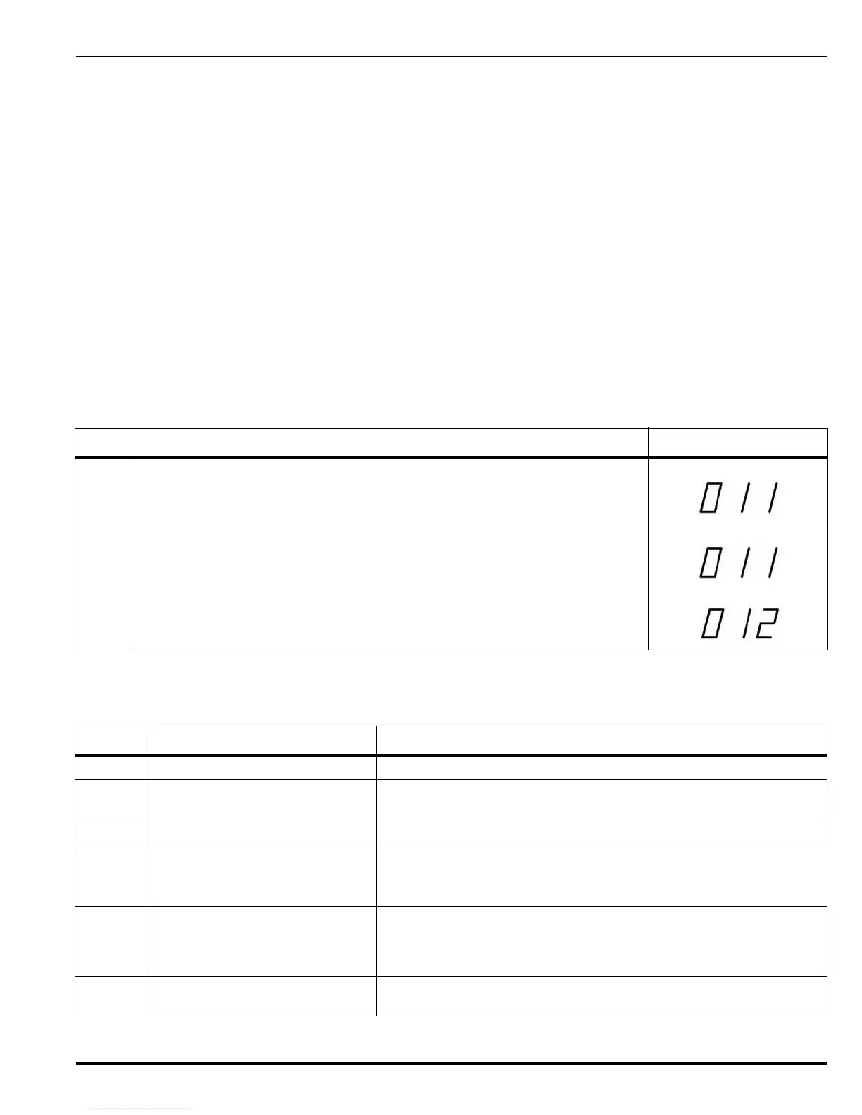
Step Description Display Examples
1 Press and hold the Signal Silence control switch for five (5) seconds. A 3-digit
Trouble code will be displayed until the Signal Silence control switch is
released (sample on right).
2 If multiple troubles exist, the display will blink one second on, one second off,
and the trouble codes will sequence to the next code every time the display
illuminates. When all codes have been displayed, the sequence will repeat until
the Signal Silence control switch is released (sample on right).
Code Trouble Corrective Action
000 Microprocessor or PCB Replace the PCB.
001 Ground Check for connections to earth ground on field wiring whose removal
restores proper earth-ground offset voltage of 6.60 Vdc nominal.
002 AC Voltage below 85% Check incoming AC power.
003 Primary PSU Output Voltage Check power supply connector, from the power supply to main PCB
(PSU J2).
Replace the power supply assembly.
004 No Secondary Power Connected Verify battery connections to PCB (TB12). In the presence of primary
power, no chargeable batteries can be detected. Either they are too
discharged (<17V), or not connected at all. In either case there will
be no battery charging.
005 Battery Charger Fault Measure Power Supply voltage (27.6 Vdc) (PSU J2). If correct,
replace PCB. If not correct, replace power supply.
 Loading...
