Installation
P/N 06-236716-001 2-11 August 2007
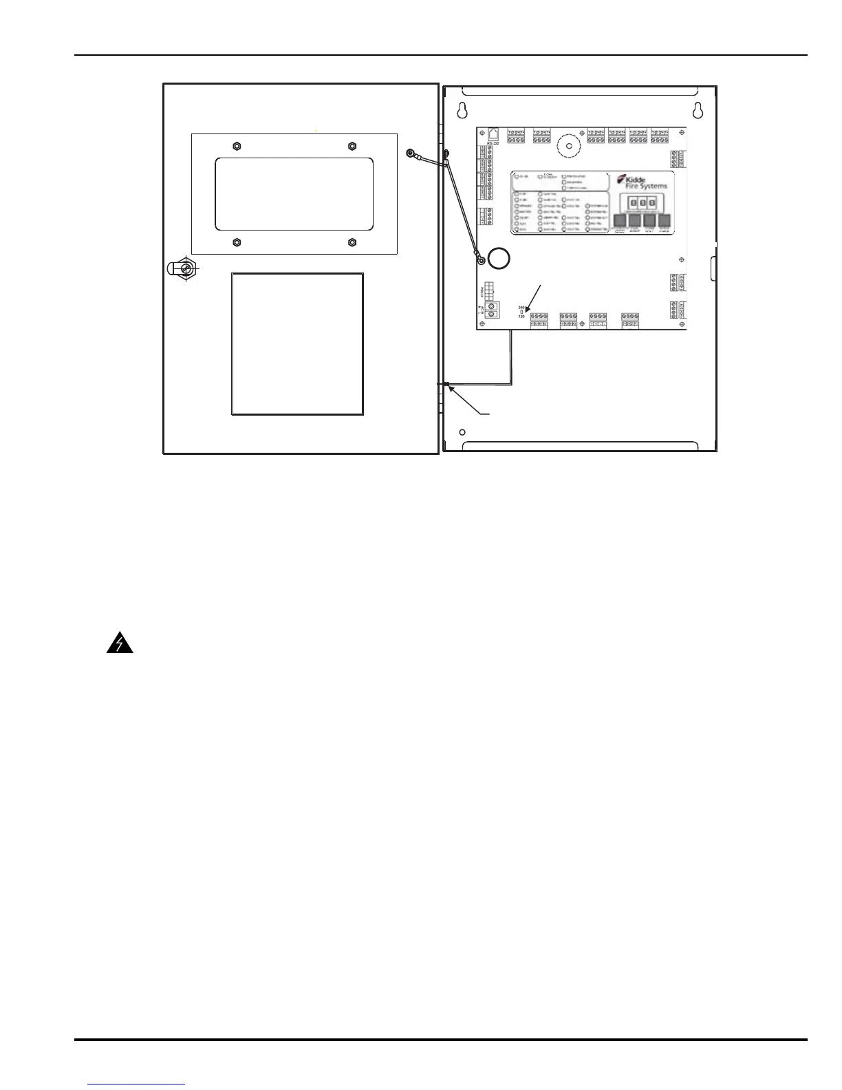
Figure 2-9. PCB-to-Cabinet Grounding Diagram
2-3.4 AC Input and Battery Backup Connections
The control unit uses AC power (by others) as the primary power source, together with a 24 Vdc
standby battery.
2-3.4.1 CONNECTING AC POWER
AC power must be provided to the control unit using a 3-conductor 14 AWG cable. The AC
power cable shall be run through a one-inch conduit from a dedicated, 15-ampere circuit
breaker. The conduit must be attached to the left side of the enclosure through one of the
upper left corner knockouts.
Perform the following steps to connect AC power to the control unit.
1. Ensure the circuit breaker at the dedicated AC power source is in the OFF position.
2. To ensure correct AC supply supervision, for 110-120 Vac operation, move the AC Supply
Select Switch (S6) on the PCB to the 120 position. For 220-240 Vac operation, move it to
the 240 position.
3. Attach the 3-conductor AC power cable to TB13 on the PCB.
WARNING
Use caution when connecting AC power to the control unit. High-voltage and
AC-powered circuits are present in the control unit. Be sure to take suitable
precautions and to adequately ground the control unit to reduce the risk of
electrical shock.
TB1
TB2
TB3TB4
TB5
TB6
TB7
TB8
TB9
TB10
TB11
TB12
TB17
TB16TB15
TB14
TB19
TB18
TB13
AC SUPPLY SELECT SWITCH (S6)
EARTH-GROUND TERMINAL FOR
POWER SUPPLY AND GREEN
WIRE OF AC SUPPLY
A
 Loading...
