Table 6-2 Polarity setting methods for digital input signals
Input/output port
selection
0: Output port
1: Input port
Channel
selection
Input: 1-7
Output:
1-5
0: The input port is valid when no current passes the
port, and the output port is valid when the switch tube
is open..
1: The input port is valid when the current passes the
port, and the output port is valid when the switch tube
is closed.
Other: Check the current status
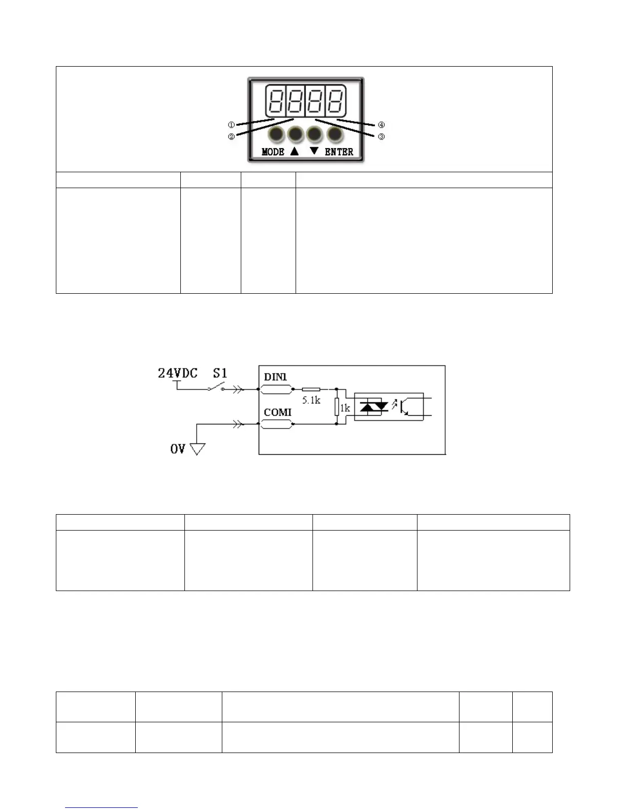
Example 6-1: Polarity Setting for Digital Input Signal DIN1
Fig. 6-1 Polarity setting for digital input signal DIN1
Table 6-3 Polarity setting for digital input signal DIN1
Input/output port selection
Set to 1 (input port
selected)
Channel selection
Set to 1 (DIN 1 selected)
0: D1N1 is enabled when S1
opens
1: D1N1 is enabled when S1
closes
Namely, if d3.08 is set to ―110.0‖, it indicates that DIN1 is enabled when no current passes the input port; if
d3.08 is set to ―110.1‖, it indicates that DIN1 is enabled when any current passes the input port.
6.1.2 Simulation of Digital Input Signals
Table 6-4 IO simulation variable
Simulates input signals, and enforces output
signals for outputting