The factory default settings for the driver are as follows: When no signal is inputted to DIN3, the driver
operates in the ―-4‖ mode (d3.16 = -4); when signal is inputted to DIN3, the driver operates in the ―-3‖ mode
(d3.17 = -3). If the driver is required to operate in the torque mode (―4‖ mode), please set d3.16 or d3.17 to 4.
In case d3.16 = 4, if DIN3 has no input signals when the driver is powered on, the driver operates in the ―4‖
mode. In case d3.17 = 4, if DIN3 has input signals, the driver operates in the ―4‖ mode.
Step 3: After configuring functions on digital input ports, select the analog – torque channel, and set
parameters such as analog – torque factors, dead zone, offset, filtering, speed limit factors, and max speed
limits.
Step 4: Save parameters.
Example 7-7: Analog – torque mode (without setting the dead zone voltage
and offset voltage)
Requirement: DIN1 is used for enabling the driver, DIN2 is used for error resetting, and DIN3 controls the
operation modes of the driver (the mode is ―4‖ when no signal is inputted, and is ―3‖ when signal is inputted).
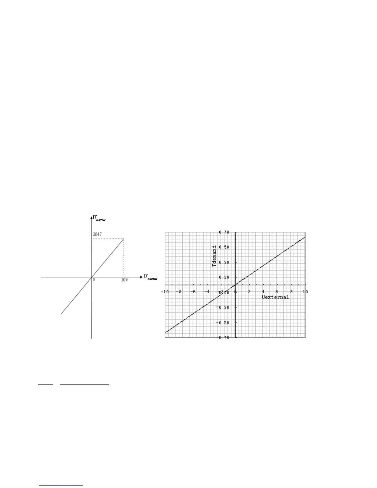
The motor Kt is 0.48 Nm/A, and the peak current of drivers is 15 A. The analog input voltage -10 V
corresponds to -0.64 Nm, and 10 V corresponds to 0.64 Nm. Select analog channel 2 (AIN1) to control the
torque.
Fig. 7-12 Schematic diagram of Example 7-7
Calculate