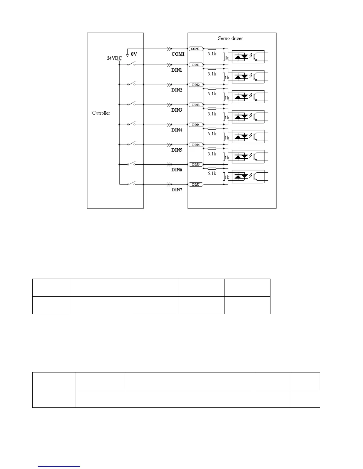
Fig. 6-3 PNP wiring diagram (to the controller that supports high level output)
6.2 Digital Output Signals
6.2.1 Polarity Control on Digital Output Signals
Table 6-14 Variables for setting simplified IO polarity
Dio_Polarity (simplified IO polarity settings) is used to set the polarity of valid digital output signals. The
number ―1‖ indicates normally open, and ―0‖ indicates normally close.Default is 1.
6.2.2 Simulation of Digital Output Signals
Table 6-15 IO simulation variables
Simulates input signals, and the output signal is
outputted compulsorily
Dio_Simulate (IO simulation) is to simulate the output of a valid signal. The number ―1‖ indicates that the
output signal is valid, and ―0‖ indicates that the output signal is invalid.