In the ―4‖ analog – torque mode, signals are output after the
max restricted speed is reached.
The driver enables the motor.
Motor is in the status of position limiting.
Example 6-6: “Ready” settings
Requirement: The digital output port 1 is defined as the ―Ready‖ function. For details on settings, see
Table 6-23.
Table 6-19: ―Ready‖ settings
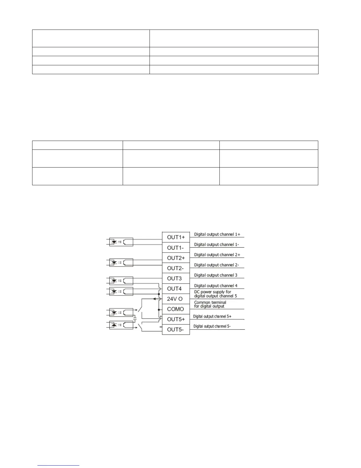
6.2.5 Wiring of Digital Output Port
1. Internal circuit diagram of digital output ports
Fig. 6-4 Internal circuit diagram of digital output ports
Note: To apply the OUT3 or OUT4 port, the COMO port must be connected. To apply the OUT5 port, both the
24VO and COMO ports must connect to the external input power.
2. NPN wiring (to controllers that support valid low level input)