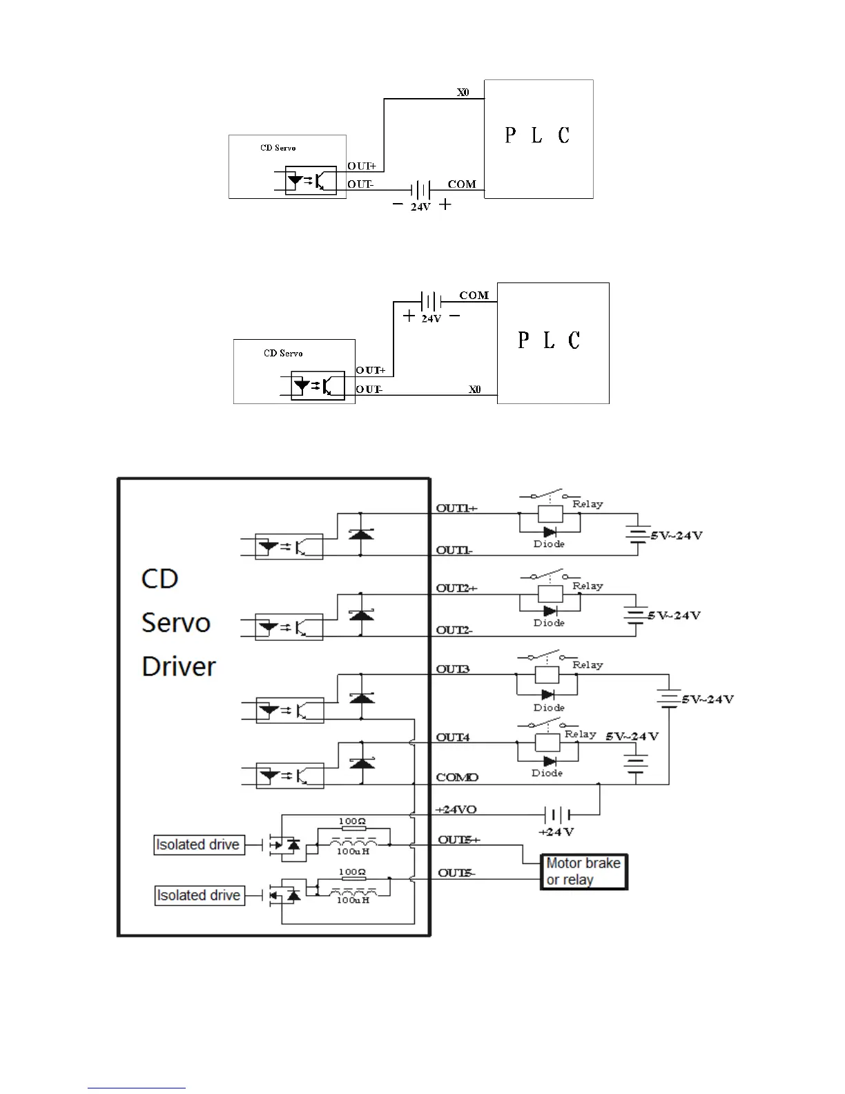
Fig. 6-5 NPN wiring diagram (to controllers that support valid low level input)
3. PNP wiring (to controllers that support valid low level input)
Fig. 6-6 PNP wiring diagram (to controllers that support valid low level input)
4. To connect a relay to the digital output port, do remember to connect a diode in inverse parallel, as
shown in Fig. 6-7.
Fig. 6-7 Connect a relay to the digital output port