Chapter 3 Interfaces and Wirings of CD Driver
3.1 Interfaces of CD Driver
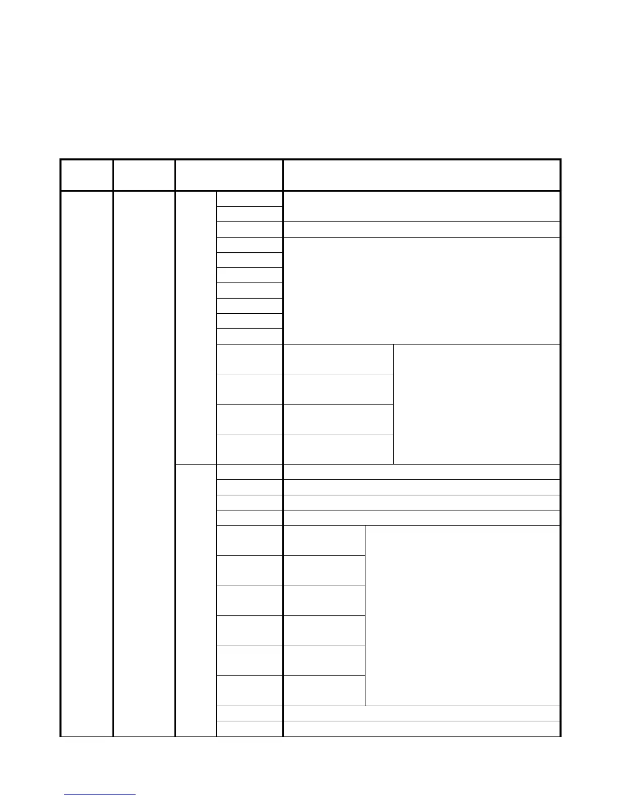
Table 3-1 Interfaces of a CD driver
External logic power (24 V +/- 15%) interface with a minimum
of 0.5 A current output
Common port of digital input signals
Digital input interface
Valid signal: 12.5 V ~ 24 V
Invalid signal: less than 5 V
Pulse or positive pulse
interface (+)
Input voltage range: 3 V to 5 V
If the input voltage is 24 V, the
interface is cascaded to the 2K
resistance.
Pulse or positive pulse
interface (-)
Direction or negative
pulse interface (+)
Direction or negative
pulse interface (-)
Analog signal input interface 1. Input impedance: 200 K
Analog signal input interface 2. Input impedance: 200 K
Digital output
interface 1+
Maximum output current: 100 mA
Withstanding voltage:24V
Digital output
interface 1-
Digital output
interface 2+
Digital output
interface 2-
Digital output
interface 3
Digital output
interface 4
Power input port of digital output signals 5
Common port of digital output signals