Sets dead zone data for external analog
signal 2
Sets offset data for external analog
signal 2
Selects analog - torque channels
0: Invalid analog channel
1: Valid analog channel 1 (AIN1)
2: Valid analog channel 2 (AIN2)
Valid mode 4
Sets the proportion between analog
signals and output torque (current)
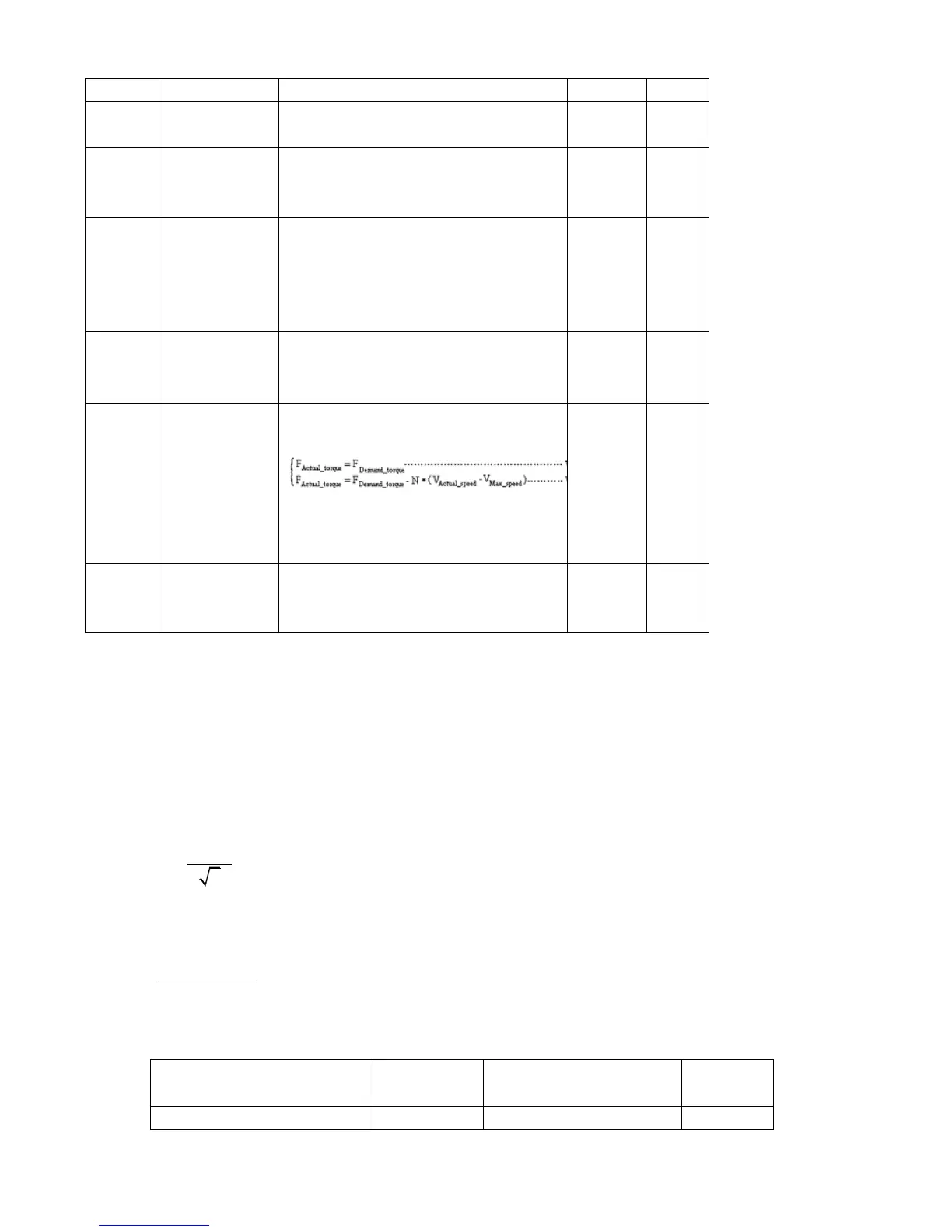
The factor that limits the maximum
speed in the torque mode
V
max_speed
complies with d2.24
Max_Speed_RPM parameter settings.
Limits the max rotation speed of the
motor
7.3.3 Analog Signal Processing
In the analog – torque mode, external analog command signals are directly inputted to the current loops
in the driver, thus directly controlling target current through the internal current loop. Analog signal is
processed in the same way as that in the analog – speed mode.
In the analog – torque mode,
is calculated according to the specified
is calculated according to
*
*
2048*2048
filter
demand
Factor U
I Ipeak
indicates the peak current of a driver).
Table 7-17