6.2.3 Status Display of Digital Output Signals
Table 6-16 Variables for status display of digital output signals
Din_Status (hexadecimal) displays the status of actual external output signals in real time.
6.2.4 Addresses and Functions of Digital Output Signals
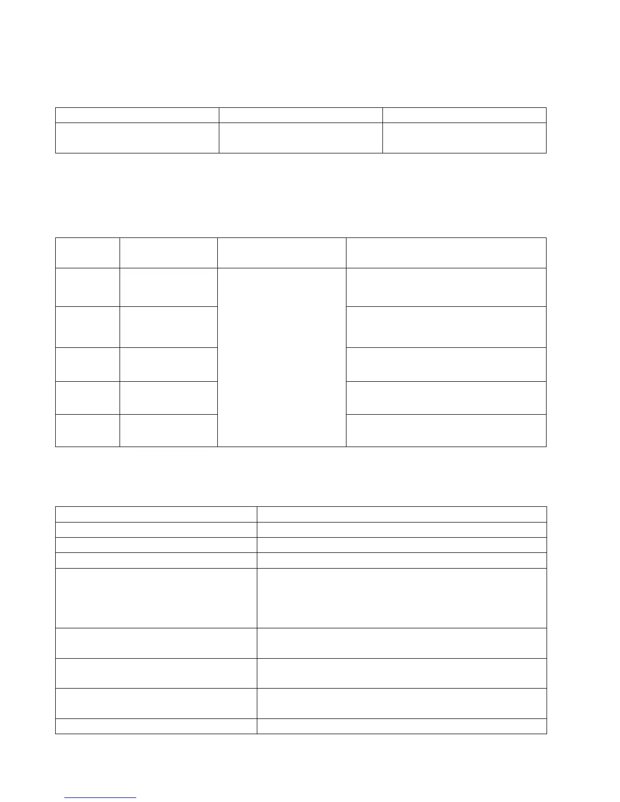
Table 6-17 Addresses and default functions of digital output signals
000.0: Disable
000.1: Ready
000.2: Error
000.4: Position reached
000.8: Zero velocity
001.0: Motor brake
002.0: Velocity reached
004.0: Index
008.0: Max. velocity limit
010.0: PWM ON
020.0:Motor limiting
040.0:Reference found
00a.4 (Position reached/Velocity
reached/Max. velocity limit)
DinX_Function (X ranges from 1 to 5) is used to define the functions of digital output ports. User can
freely define the functions of digital output ports according to actual applications.
Table 6-18 Meanings of the functions defined by digital output signals
Cancel the function of this digital output
The driver is ready for operation.
Alarm signals are output, indicating that the driver is faulty.
In the ―-4‖ mode of pulse control, the target position data keeps
unchanged in the window (d3.39) of the time of reaching the
target position, and position errors are within the window of
reaching the target position.
After the motor is enabled, it is outputted when the motor speed
is 0.
The driver enables the motor, and contracting brake output is
valid.
In the ―-3‖ or "3‖ internal speed control mode, signals are output
after they reach the target speed.
Z phase signal output (the speed should not be too high).