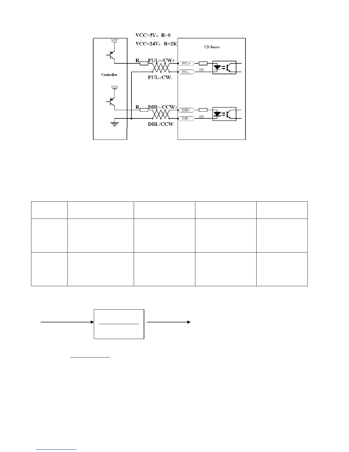
Fig. 7-3 Common cathode connection (to controllers that support valid high level output)
7.1.2 Parameters for Pulse Control Mode
1. Parameters for electronic gear ratio
Table 7-1 Parameters for electronic gear ratio
Parameters for electronic gear ratio are used to set the numerator and denominator of electronic gears when
the driver operates in the ―-4‖ mode.
Command pulse input Command pulse output
F1 F2
Namely: F2=
* F1
If the electronic gear ratio is 1:1, 10000 pulses are inputted externally (the resolution of encoders is 2500
PPR, quadruple), and the motor turns a circle. If the electronic gear ratio is 2:1, 10000 pulses are inputted
externally, and the motor turns two circles.
2. Parameters for pulse mode selection
Table 7-2 Parameters for pulse mode selection