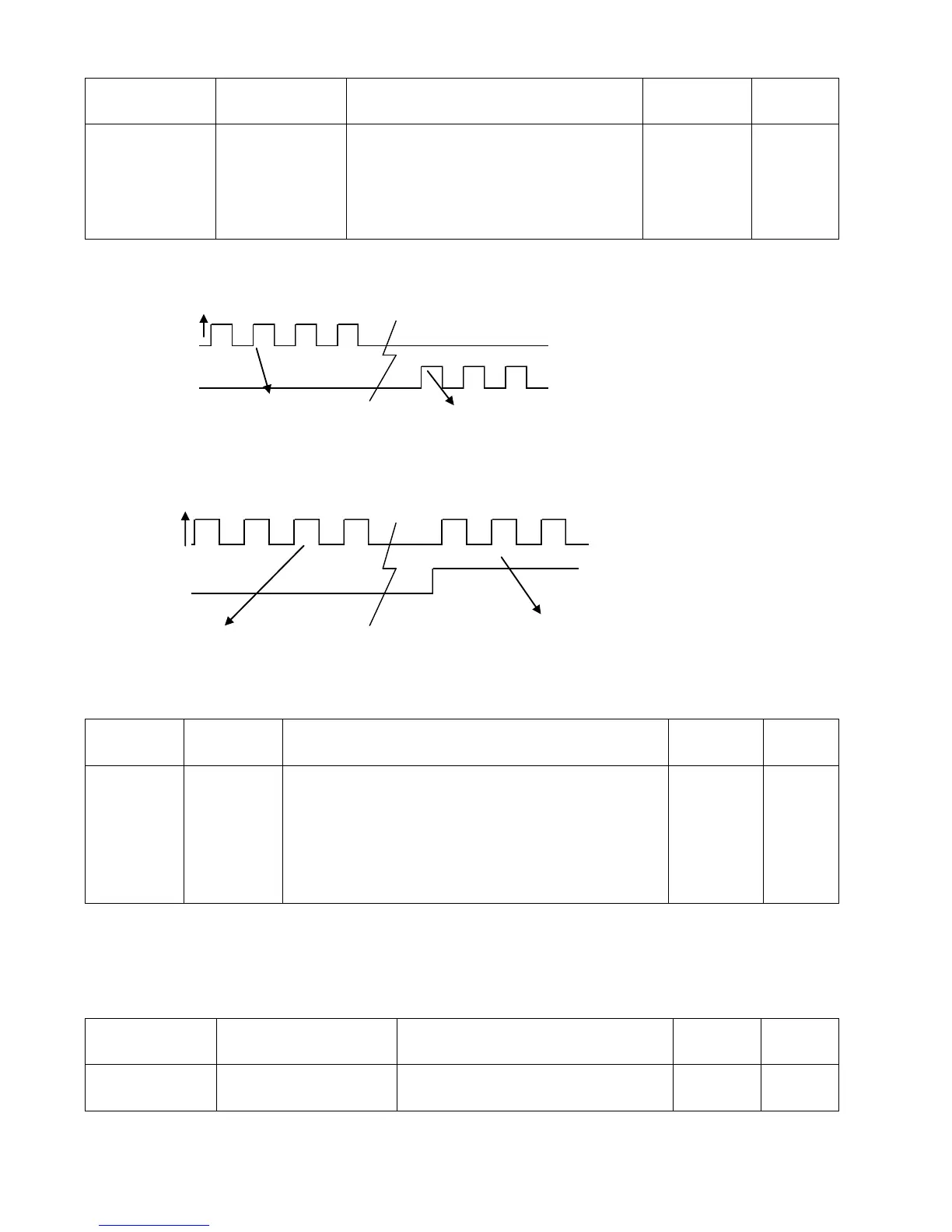
0: Double pulse (CW/CCW) mode
1. Pulse direction (P/D) mode
Note: To change this parameter, you
need to save it with d3.00, and restarts it
later.
Note: AB phase signals are not supported.
Double pulse (CW/CCW) mode (d3.36 = 0)
Pulse direction (P/D) mode (d3.36 = 1)
3. Parameters for pulse filtering coefficient
Table 7-3 Parameters for pulse filtering coefficient
Used to smooth the input pulses.
Filter frequency: f = 1000/(2π* PD_Filter)
Time constant: T = PD_Filter/1000
Unit: S
Note: If you adjust this parameter during the operation,
some pulses may be lost.
When a driver operates in the pulse control mode, if the electronic gear ratio is set too high, it is required
to adjust this parameter to reduce motor oscillation; however, if the parameter adjustment is too great, motor
running instructions will become slower.
4. Parameters for pulse frequency control
Table 7-4 Parameters for pulse frequency control
Indicates the limitation on pulse input
frequency (kHz)
5. Parameters for gain control on position loops and velocity loops
Effective on the
rising edge
Effective on the
rising edge