Fig. 7-7 Schematic diagram of Example 7-3
Calculate
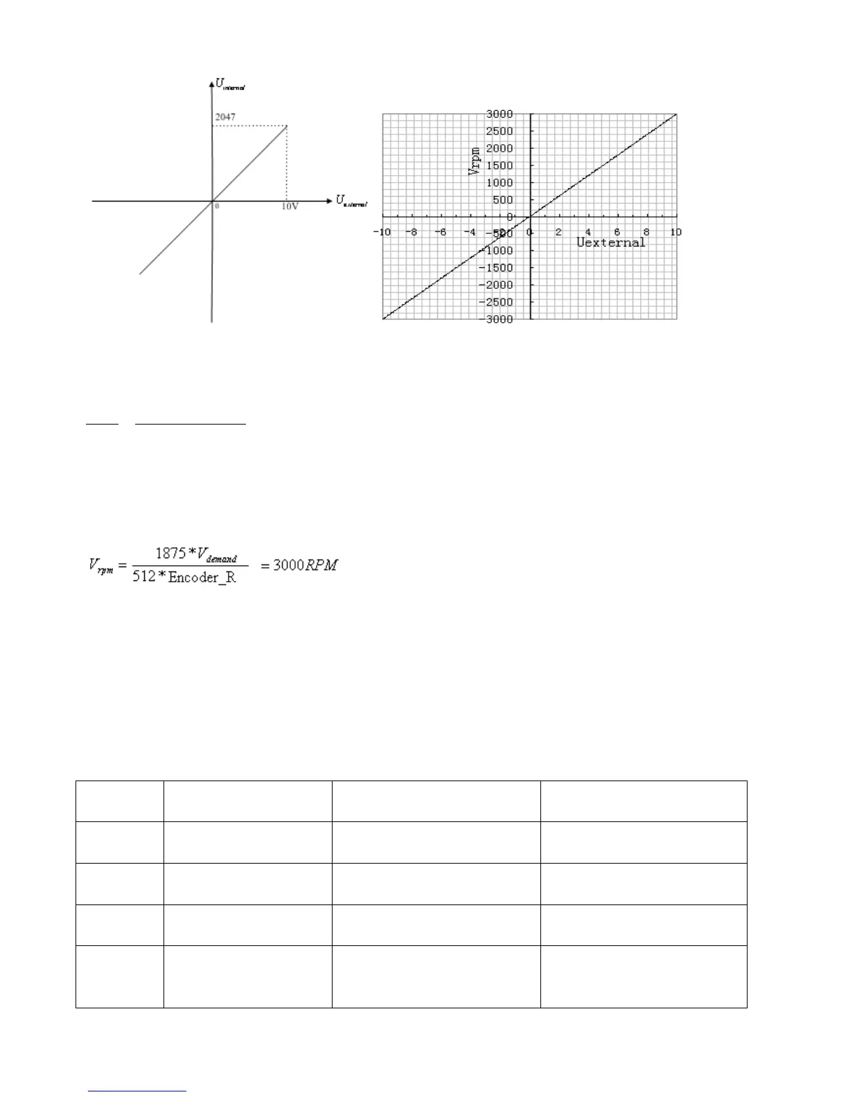
according to the offset voltage and dead zone voltage that require settings:
2047
10 10
filter
shift dead
U
v v U U
according to the required speed
:
(Encoder_R is 1000 inc/r)
Result:
*
demand filter
V Factor U
Table 7-12 Parameter settings in Example 7-3
Define the functions of digital
input port 1
Define the functions of digital
input port 2
Define the functions of digital
input port 3
000.4 (Control over operation
modes of drivers)
Define the functions of digital
input port 5
The default value 001.0
changes to 000.0 (position
positive limits are disabled)