EasyManuals Logo

Kleemann GENIUS20 User Manual

Default Icon
233 pages
To Next Page IconTo Next Page
To Previous Page IconTo Previous Page
Page #15 background imageLoading...
Page #15 background image
15
MA06-03-1-01
Menu
When a call is registered in a released landing, green symbols turn blue with either a white dot in
the centre (car call) or white arrows indicating the onward direction (landing call).
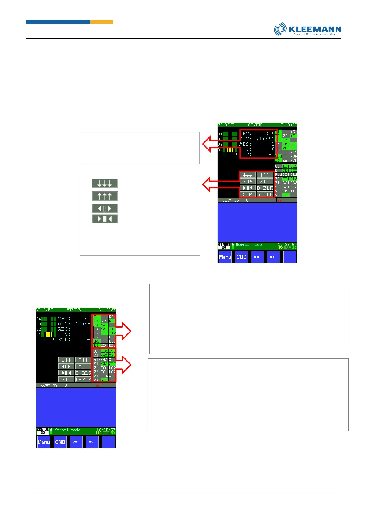
Above the entire illustration, the landing number (here red “0”) marks the current lift position.
During operation, the opening and closing state for 2 doors with the respective times (in seconds)
is indicated.
On the right you can find the most important controller signals, such as:
TRC = Travel counter
OHC = Operating hours counter
V = Current speed
STP = Step
= Travel to lowest landing
= Travel to highest landing
= Door 1/2 opened
= Door 1/ 2 closed
SIM = Simulator de-/activate
SL = Shaft light on/off
D-BLK = Block door
L-BLK = Landing call on/off
S1-6 = Safety circuit 1-6
K5 = K5 safety relay
MON = Contactor monitoring
K7 = K7 safety relay
L4 = Car light
VO = Upper prefinal switch
OT1 = Overtemperature 1
SZ = Signal switch zone
OT2 = Overtemperature 2
SM = Signal switch center
REC = Recall
VU = Bottom prefinal switch
RUP = Recall up
ES = Emergency Stop
RDN = Recall down
UP = Direction up
LS1/2 = Light curtain 1/ 2
DN = Direction down
OB1/2 = Obstruction door 1/ 2
RUN = Inverter travel
OL1/2 = Open-limit switch door 1/ 2
V0 = Inverter speed 0
CL1/2 = Close-limit switch door 1/ 2
V1 = Inverter speed 1
DO1/2 = Door 1/ 2 open
V2 = Inverter speed 2
DC1/2 = Door 1/ 2 close
V3 = Inverter speed 3
KFN = Car fan
VN= Inverter rated speed
KL = Car light
AL = Alarm

Questions and Answers:

Question and Answer IconNeed help?

Do you have a question about the Kleemann GENIUS20 and is the answer not in the manual?

Kleemann GENIUS20 Specifications

General IconGeneral
BrandKleemann
ModelGENIUS20
CategoryController
LanguageEnglish