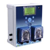
Figure 51. Klereo Therm n°1 wiring solution
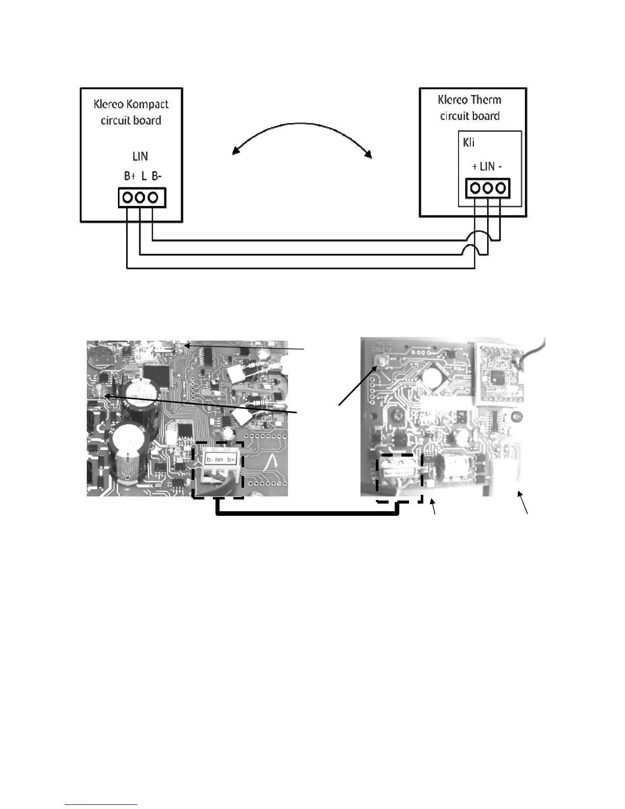
Figure 52. Connecting the K-link communication bus line: wiring n°1
Connect the K-link bus lines of both control box units while respecting the B+ ; lin and B-
connections.
Klereo Therm printed circuit board is located inside the heating pump..
To match the Klereo Therm heating pump, proceed as follows:
1- Press the orange matching key button (as shown on picture 52) on the Klereo Therm
circuit board till LED 2 flashes rapidly then stops and after LED 1 flashes rapidly.
2- Release the key button
3- Press briefly the orange matching key button (as shown on picture 52) on the Klereo
Kompact circuit board till the LED flashes rapidly.
4- The Klereo Therm circuit board LED 1 turns on steady (it means that matching has
been successful)
Orange
matching
key button
LED 2
Matching